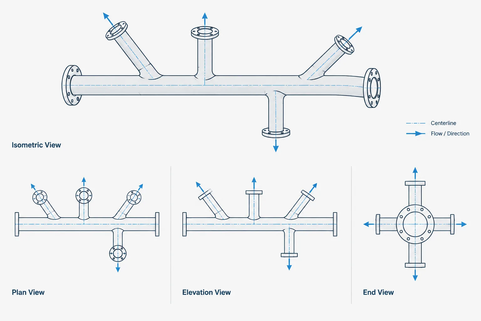
Branch connection orientation in piping CAD is a geometric control issue, not merely a drafting preference. A branch may be located at the correct station and use the correct connection while still pointing in the wrong radial or spatial direction. Clear orientation data helps the model, isometric, spool drawing, and fabricated assembly communicate the same design intent.
This guide explains how clocking, plant coordinates, centerline geometry, viewing direction, and end-view details work together. It also highlights why terms such as top, bottom, and side require careful interpretation when a run is sloped, vertical, or skewed.
A piping branch is not fully defined by its size and connection type. Its direction must also be controlled. A branch connection may point upward, downward, horizontally, or at an intermediate angle around the run pipe. If that orientation is unclear, a geometrically correct model can still produce an incorrect spool, interfere with nearby equipment, or place a vent, drain, valve, or instrument where it cannot be used.
Branch connection orientation is especially important for branch outlet fittings, fabricated stub-ins, reducing tees, lateral connections, vents, drains, and small-bore attachments. The designer must communicate more than the appearance of the branch in one view. The model and drawings should establish the run centerline, branch centerline, intersection or fitting location, and directional reference used to define the branch.
What Branch Orientation Actually Controls
Branch orientation describes the direction in which the branch centerline leaves the run. For a straight horizontal run, common descriptions include top, bottom, and side outlet. These terms are convenient, but they may not provide enough control for a rotated, sloped, or skewed run.
A complete branch definition generally involves several independent pieces of information:
- The location of the branch along the run centerline
- The branch nominal size and connection type
- The angle between the run and branch centerlines
- The rotational position of the branch around the run
- The direction in which the branch continues after leaving the run
- The reference coordinate system or view used to interpret that direction
The branch angle and rotational position are not the same. A branch can be perpendicular to the run while still being rotated to many different positions around it. Conversely, a lateral branch can have both a non-perpendicular centerline angle and a specific rotational orientation.
Top, Bottom, and Side Are Relative Terms
On a level horizontal pipe, a top branch usually points vertically upward, while a bottom branch points vertically downward. A side branch normally leaves the run horizontally. Once the run is sloped, vertical, or skewed in plan, those descriptions become less reliable.
For example, “top of pipe” can mean the point on the pipe circumference that is locally above its centerline. That local radial direction may not match a branch that is required to be globally vertical. This distinction matters on sloped drain lines, inclined headers, and three-dimensional offsets.
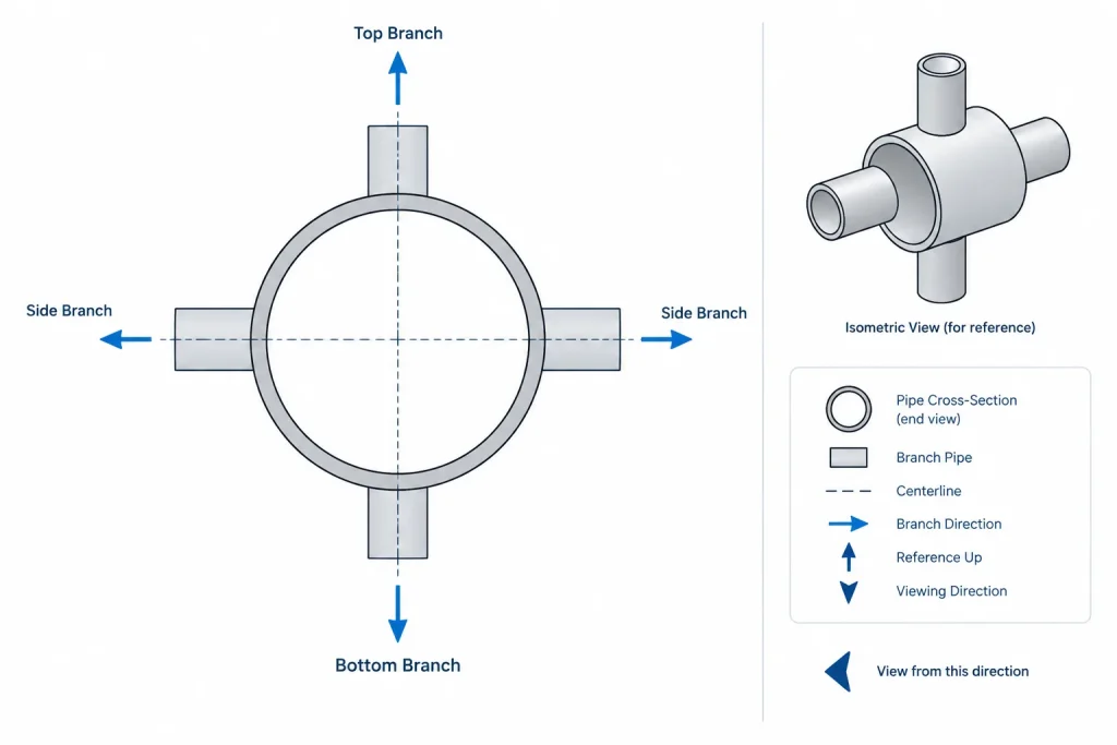
Before using orientation notes, determine whether the project intends them to describe:
- A global direction such as plant north, east, up, or down
- A direction relative to the run pipe itself
- A direction as viewed along the run centerline
- A drafting convention used only in a particular plan, section, or isometric
When the interpretation could change with the view, coordinates or an explicit directional note are safer than an informal label.
Using Clocking to Describe Rotation
Clocking is a convenient way to describe rotational position around a pipe centerline. The run is imagined as being viewed end-on, and the branch direction is described by its position around that circular view. This approach can be useful for branch outlets, instrument taps, trunnions, vents, drains, and other radial attachments.
However, clocking is incomplete unless the viewing direction is stated. Looking from one end of a pipe reverses the apparent rotation compared with looking from the other end. Projects may also use different zero references or drafting practices. A clock position should therefore never be assumed to be universal.
Information Needed for an Unambiguous Clocking Note
- The line or spool being viewed
- The viewing direction along the run
- The reference direction treated as the top of the view
- The specified branch or attachment being clocked
- Whether the orientation is nominal or requires fabrication control
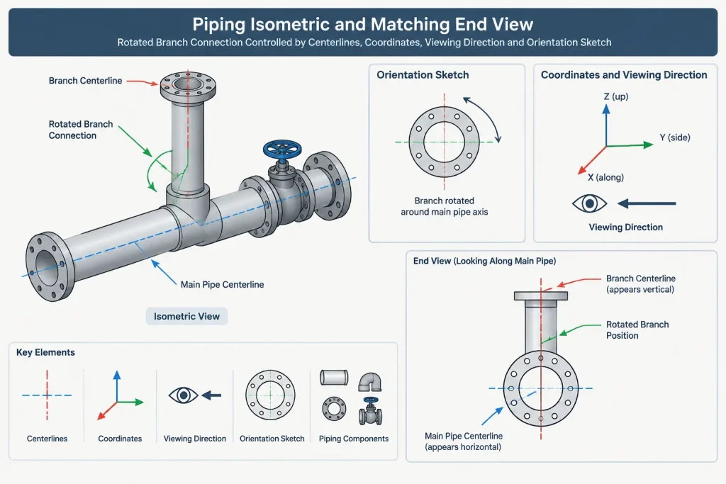
A small end-view detail is often clearer than a clock note by itself. The detail can show the run cross-section, a reference-up arrow, the viewing direction, and the radial branch centerline without depending on visual interpretation from a crowded isometric.
Coordinate-Based Orientation
Coordinates provide a stronger control method when branch endpoints or centerline points are known. If the branch origin and another point on its centerline are defined in the same coordinate system, the direction can be reconstructed without relying on the apparent angle in a drawing view.
Coordinate control is particularly useful for:
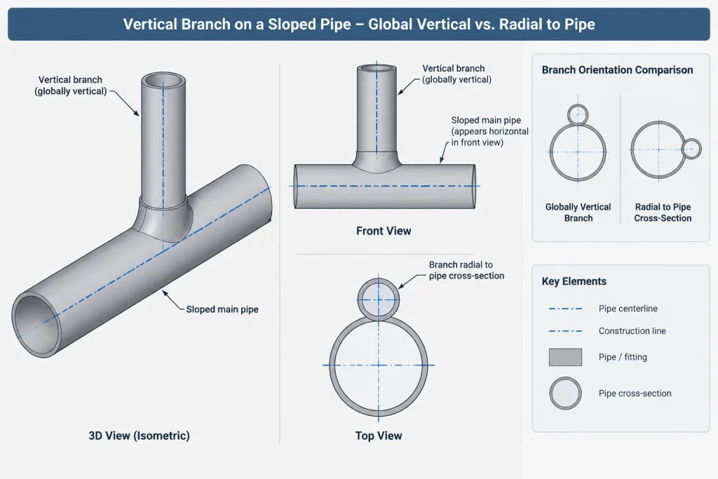
- Branches connecting to equipment nozzles
- Skewed lines that do not follow principal plant axes
- Branches passing through structural or architectural openings
- Prefabricated spools with rotated outlets
- Interfaces between separate CAD models or vendor packages
Coordinates do not eliminate the need for good graphics. A drawing should still make the branch direction visually understandable. Coordinate callouts serve as controlling data, while views and symbols help reviewers recognize errors.
Choosing the Correct Geometric Reference
Branch orientation should normally be based on centerline geometry rather than on the visible edge of the pipe or fitting. Pipe outlines change with outside diameter, insulation, and display style, while the centerline remains the primary routing reference.
| Reference | What It Controls | Common Risk |
|---|---|---|
| Run centerline | Main routing axis and branch station | Using an outside surface as the location reference |
| Branch centerline | Direction of the outgoing connection | Judging orientation from a projected view |
| Centerline intersection | Theoretical relationship between run and branch | Confusing the intersection with a cut length or fitting end |
| Fitting or outlet end | Connection point for downstream piping | Assuming all branch types have the same takeoff geometry |
| Global coordinate axes | Plant-wide directional control | Mixing local equipment axes with plant coordinates |
A reducing tee, branch outlet fitting, and fabricated stub-in can place their physical ends differently even when their centerline intersection is identical. The CAD component must therefore use geometry appropriate to the selected branch type. Rotating a generic symbol into position does not establish the correct takeoff, weld location, or end connection.
Branch Orientation on Isometric Drawings
An isometric drawing is a projected representation, not a direct measurement of spatial angle. A branch may appear vertical, diagonal, or horizontal on the sheet because of the projection and line direction. Fabrication orientation should not depend only on how that line looks.
An isometric can control the branch using a combination of:
- Centerline dimensions locating the branch station
- Elevations or coordinates for branch points
- Directional labels or axis references
- Clocking or rotation details
- End-view sketches for radial outlets
- Notes identifying vertical, horizontal, or sloped continuation
Dimensions should describe the intended geometry without forming conflicting closed loops. If coordinates, angular notes, and linear dimensions all control the same endpoint, they must agree and their priority should be clear.
Special Cases That Need Extra Attention
Vents and Drains
A vent connection generally needs to communicate its relationship to the high point, while a drain connection must relate to the low point and drainage path. Simply placing the branch near the top or bottom of a projected view does not prove that it occupies the actual high or low radial position on a sloped pipe.
Small-Bore Branches
Small branches are often simplified in a model or represented with symbolic geometry. Their valves and fittings may need room for operation, insulation clearance, welding, and support. The branch centerline orientation should be established before downstream components are arranged.
Fabricated and Angled Branches
A fabricated branch may require information beyond radial clocking, including the centerline intersection angle, contour location, weld identification, and spool ownership. An angled branch should not be inferred from a pictorial view when its geometry affects fabrication.
Branches on Vertical Runs
Terms such as top and bottom are not useful for radial orientation around a vertical run. Plant directions, coordinates, or a plan view usually provide clearer control. The viewing direction for any clocking detail must still be stated.
A Practical CAD Review Workflow
- Confirm the reference system. Verify the project coordinates, plant directions, elevation datum, and any local equipment axes.
- Locate the branch station. Check the centerline intersection or component insertion point against the controlling layout.
- Verify the branch type. Confirm that the modeled tee, outlet, lateral, or fabricated connection matches the piping specification and design intent.
- Inspect the direction in multiple views. Use plan, elevation, section, and end views rather than relying on one isometric view.
- Check slope and skew. Determine whether “up,” “down,” or “side” refers to global coordinates or the local pipe cross-section.
- Review downstream access. Check valves, instruments, removable items, insulation, structures, and maintenance space.
- Compare deliverables. Reconcile the model, isometric, general arrangement, P&ID intent, and spool information.
- Flag uncertain field interfaces. Existing-pipe orientation and actual attachment locations may require field measurement before fabrication.
Document Intent, Not Just Appearance
Good branch documentation allows another person to reconstruct the intended geometry without opening the original designer’s model or guessing from a projected line. The most reliable approach combines centerline-based modeling, a defined coordinate system, clear viewing directions, and additional end views where radial orientation matters.
Before issuing a drawing or spool, ask whether the branch would remain unambiguous if the sheet were rotated, the model display changed, or the component were viewed from the opposite end. If the answer is no, add a controlling direction, coordinate, or orientation detail. That small addition can prevent a branch from being fabricated correctly in every respect except the direction it points.
Establish a Controlling Orientation Record
Where several documents describe the same branch, the project should identify which information controls and which information is provided for visual confirmation. A model view, coordinate callout, clocking note, and isometric dimension can appear consistent while being based on different origins, axes, or viewing directions.
A useful orientation record should connect the branch to a stable geometric reference. Depending on the design workflow, that record may include:
- The run centerline and branch station used to locate the connection
- The branch centerline or a defined point along its continuation
- The plant or local coordinate system applied to the geometry
- The viewing direction used by any clocking detail
- The reference-up direction shown in an end view
- The document or model property treated as controlling
- The revision status shared by the model, isometric, and spool information
This information is especially valuable at model interfaces. Equipment models, vendor packages, structural models, and piping models may use different local origins or axis conventions. Orientation should be checked after coordinate transformation rather than accepted from appearance alone.
Resolve Conflicts Before Fabrication
If an end view, coordinate, note, and projected line do not agree, the discrepancy should be resolved rather than interpreted in the shop or field. Rotating a branch to match one view may change valve access, instrument position, drainage behavior, or the alignment of downstream piping.
The review should distinguish between a true geometric conflict and a graphic simplification. Symbolic branches, diagrammatic isometrics, and simplified small-bore components may not display their physical form accurately, but their controlling centerlines and orientation references must still express the intended direction.
Final Handoff Check
Before release, verify that a reviewer who did not build the model can identify the branch origin, outgoing direction, radial position, and applicable reference system. If that reconstruction requires guessing from the apparent direction of an isometric line, the documentation needs an additional coordinate, note, section, or end-view detail.
Frequently Asked Questions
Is branch angle the same as branch clocking?
No. Branch angle describes the relationship between the run and branch centerlines. Clocking describes the rotational position of the branch around the run centerline. Both may be needed to define an angled or lateral connection.
Why must a clocking view state its viewing direction?
The apparent rotational position reverses when the run is viewed from the opposite end. A viewing arrow, line designation, and reference-up direction prevent that ambiguity.
Should orientation be taken from the pipe surface or centerline?
Centerline geometry is normally the clearer routing reference. Visible pipe edges can vary with component geometry, insulation display, and drawing style, while the centerline defines the intended routing axis.
Can an isometric line alone define branch direction?
It should not be relied upon when fabrication orientation matters. Isometric projection can make spatial directions look misleading, so controlling dimensions, coordinates, directional notes, or end views may be required.
How should a branch on a sloped run be described?
The documentation should clarify whether the branch follows a local radial direction from the run or a global plant direction. Coordinates or a defined end view can distinguish local top-of-pipe orientation from globally vertical orientation.
What should be checked when branch information conflicts?
Confirm the coordinate system, datum, model revision, viewing direction, component type, and designated controlling document. The conflict should be resolved before spool release or fabrication rather than left to visual interpretation.