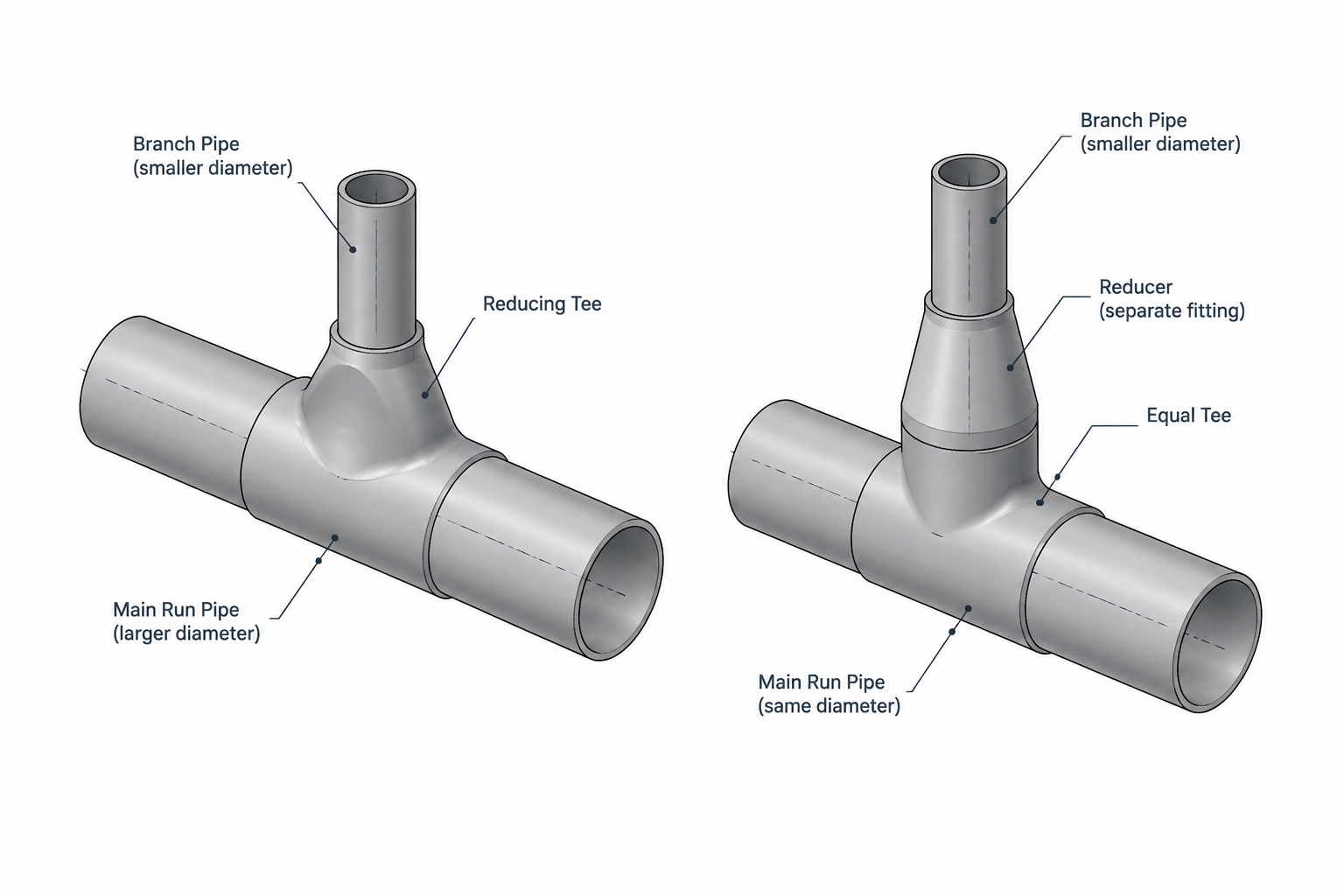
When a branch is smaller than the main pipe, the fitting arrangement influences much more than the visible transition. A reducing tee and an equal tee with a separate reducer may connect the same nominal sizes, yet they create different component sequences, physical envelopes, weld locations, and material records.
This comparison explains how to evaluate the alternatives during piping layout, specification review, fabrication planning, and CAD coordination. The final selection should be based on verified component data and project requirements rather than apparent centerline equivalence.
A branch that is smaller than its main pipe can often be arranged in more than one way. Two common options are a reducing tee or an equal tee followed by a separate reducer in the branch. Both arrangements can connect the required nominal sizes, but they are not automatically interchangeable.
The choice affects fitting availability, weld count, branch position, material takeoff, fabrication space, inspection access, and the geometry shown in the CAD model. It may also affect process performance and maintenance, depending on where the reducer is placed and how the line operates. Designers should therefore treat this as a component-selection and layout decision rather than a simple drafting preference.
What Is a Reducing Tee?
A reducing tee has a straight run with a smaller branch outlet. The run connections are normally identified first, followed by the branch connection. Because size-order conventions can vary by component description or project system, the branch size should be confirmed from the applicable catalog, piping specification, or verified dimension record rather than inferred from text alone.
The reduction occurs within the tee body. A separate branch reducer is not required, so the assembly can be compact. In a welded system, this may also eliminate one fitting and one circumferential joint compared with an equal tee and reducer arrangement.
Reducing tees are not available in every size combination, material, wall designation, pressure class, or end-connection type. Even when a nominal combination appears commercially common, project acceptability must be checked against the governing piping material specification.
What Is an Equal Tee and Reducer Arrangement?
An equal tee has the same nominal size at its run and branch openings. To create a smaller branch, a reducer is installed downstream of the branch outlet. Depending on the connection system, this might be a butt-weld reducer, reducing coupling, swage-type component, threaded reducer, or another specification-approved transition.
This arrangement occupies more length along the branch centerline. It introduces another component and usually another joint, but it may provide useful flexibility when the required reducing tee is unavailable or when the larger branch section serves a deliberate process, maintenance, or connection function.
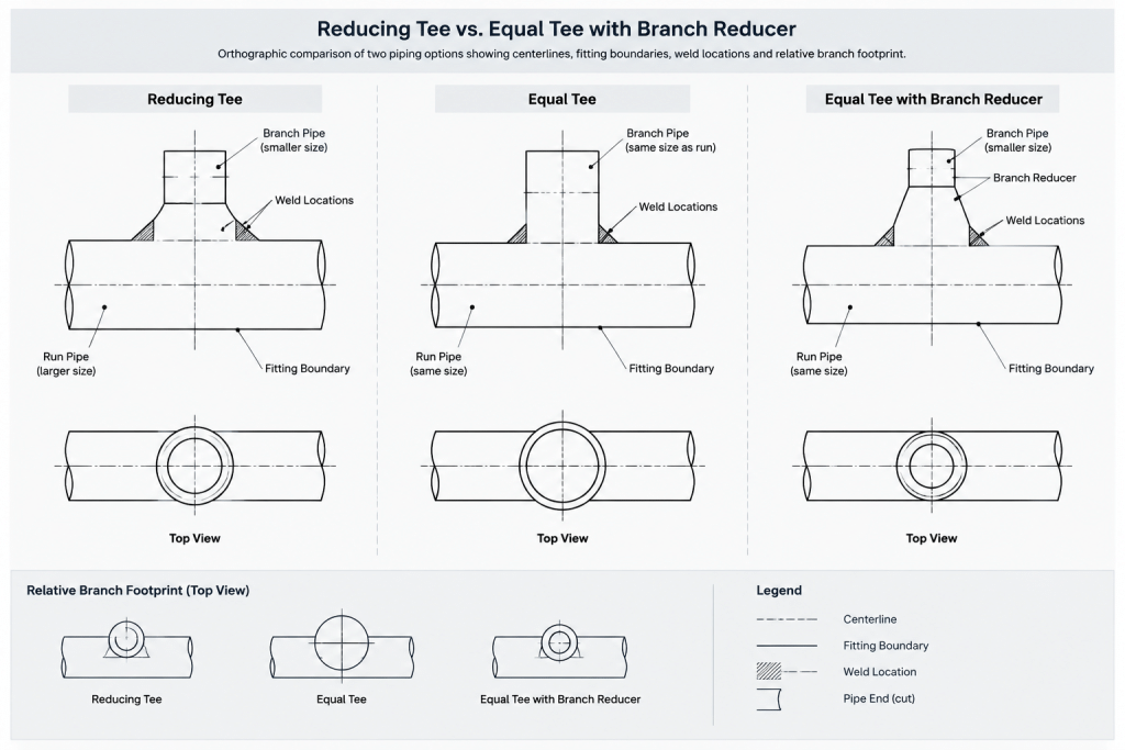
The reducer does not have to be placed directly against the tee. A piece of straight pipe may be required or preferred between components because of fabrication, welding, inspection, stress, or project-specific detailing rules. That spacing should come from verified design requirements, not from a generic CAD block.
Side-by-Side Comparison
| Consideration | Reducing tee | Equal tee plus reducer |
|---|---|---|
| Branch footprint | Usually more compact | Requires additional branch length |
| Component count | One primary fitting | Tee, reducer, and possibly intermediate pipe |
| Joint count | Typically lower | Typically higher |
| Size-combination availability | May be limited | Can offer more combinations using separate components |
| CAD definition | Requires the correct reducing-tee geometry and ports | Uses separate components with independently controlled dimensions |
| Material takeoff | Shorter item sequence | More line items and joint records |
| Field substitution | Replacement must match the required outlet arrangement | Individual components may be easier to source, subject to approval |
These are general layout tendencies, not universal selection rules. End connections, fabrication method, material class, and service conditions can change the comparison.
Layout and Dimensional Consequences
Branch takeoff location
The branch centerline normally originates at the tee center, but the point at which the smaller bore begins differs between the two arrangements. In a reducing tee, the transition is incorporated into the fitting. With an equal tee and reducer, the branch remains at the larger nominal size until it reaches the reducer.
This distinction matters when locating nearby valves, instruments, supports, flanges, or equipment connections. A model that shows only centerlines may appear equivalent even though the physical envelopes and connection points are different.
Cut lengths and fitting takeouts
Replacing one arrangement with the other changes more than the bill of materials. It can alter fitting takeout, straight-pipe cut length, weld location, support relationship, and the position of the next component. The designer should rebuild the dimension chain from verified component dimensions instead of preserving the old branch endpoint and forcing the new parts into the available space.
Outside envelope
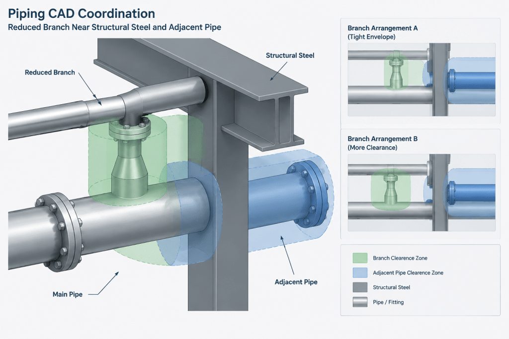
An equal tee has a full-size branch neck and may create a larger local envelope before the reducer. That envelope can affect insulation, adjacent lines, structural steel, and access for welding or examination. Conversely, a reducing tee may provide a tighter arrangement but still require adequate clearance around its branch joint.
Process and Flow Considerations
Neither option should be declared hydraulically superior without reviewing the actual service. The internal transition geometry, branch flow direction, velocity, phase behavior, erosion potential, pressure loss, and upstream or downstream equipment requirements may all matter.
A separate reducer also introduces an orientation decision when the transition is eccentric rather than concentric. The chosen orientation may be important for liquid drainage, vapor-pocket control, slurry behavior, or pump-related service. A reducing tee does not provide the same freedom to clock a separate transition.
For flow-sensitive installations, CAD should follow the engineering selection. It should not be used to choose an arrangement merely because one component is easier to place or produces a cleaner-looking model.
Fabrication, Welding, and Inspection
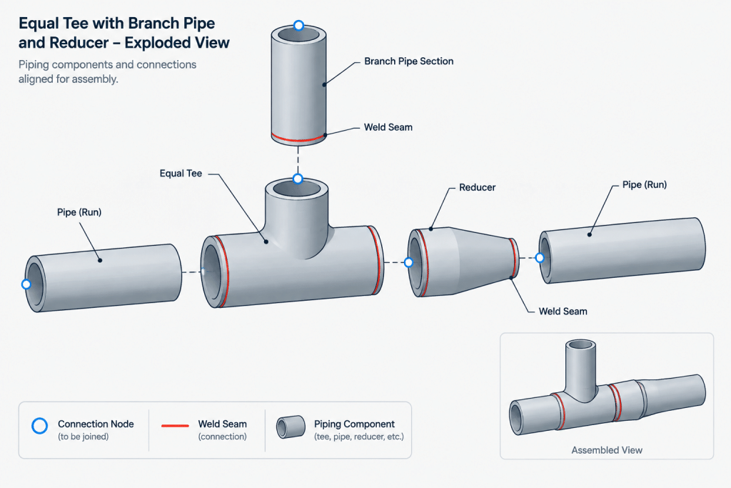
A reducing tee can reduce the number of pieces that must be fitted and tracked. Fewer joints may mean fewer weld identifiers, examination locations, and coating touch-up areas. However, this advantage has value only if the fitting is approved, available, and compatible with the connected pipe wall requirements.
An equal tee and reducer creates additional fabrication variables. The shop must control the intermediate spool length, reducer orientation, joint preparation, and alignment of the smaller branch. Very short pipe pieces may be difficult to fabricate or inspect, especially when access around adjacent welds is restricted.
The assembly may still be preferred when standard stock, procurement strategy, field replacement, or a required branch connection makes it practical. Fabrication personnel should review unusually tight arrangements before drawings are released.
How to Model the Options Correctly in CAD
- Use verified component records. Do not scale an equal tee to resemble a reducing tee or edit a reducer until it fits visually.
- Define all ports by nominal size and end type. A reducing tee should expose the correct run and branch properties so connectivity checks can detect errors.
- Preserve component identity. The model, isometric, and material report should distinguish a reducing tee from an equal tee followed by a reducer.
- Check fitting takeouts. Center-to-end and end-to-end dimensions should come from the applicable component source.
- Model the real envelope. Include the larger branch section, reducer body, insulation allowance, and weld-access area where they affect coordination.
- Review reducer orientation. If an eccentric transition is used, record its flat-side orientation clearly enough for fabrication.
- Recalculate pipe cuts. A component swap should trigger an update to adjoining straight lengths, coordinates, and spool dimensions.
Material Specification and Procurement Checks
Before selecting either arrangement, confirm that every component is permitted by the line’s piping material specification. Check the required material, end connection, wall or bore relationship, branch size combination, facing where applicable, and any service-specific restrictions.
Availability should be verified early when the arrangement depends on an uncommon reducing tee. A catalog symbol or database entry does not prove that a component is stocked, obtainable within the project schedule, or approved for the service. Similarly, constructing a transition from commonly available pieces does not make it an acceptable substitution without engineering and specification review.
A Practical Selection Workflow
-
Identify the main size, branch size, connection type, material class, and service requirements.
-
Check whether an approved reducing tee exists for the required combination.
-
Compare the verified takeout and envelope of both arrangements.
-
Review flow behavior and reducer orientation with the responsible engineer when relevant.
-
Check weld spacing, examination access, insulation, supports, and nearby components.
-
Confirm procurement availability and any project substitution process.
-
Update the CAD model, isometric dimensions, weld records, and material takeoff as one coordinated change.
Key Drafting Takeaway
A reducing tee and an equal tee with a reducer may connect the same nominal pipe sizes, but they do not create the same physical or documentary result. The two options differ in branch envelope, fitting takeout, weld count, component identity, transition location, and potentially flow behavior.
The best arrangement is the one supported by the piping specification, engineering intent, verified dimensions, fabrication needs, and procurement plan. In CAD, represent the selected assembly exactly rather than treating the alternatives as geometrically interchangeable.
Final Review: Treat the Selection as a Managed Design Change
Changing between these arrangements should be handled as a coordinated piping change, not as a graphical substitution. Review the branch from the tee centerline through the next fixed connection, including component takeouts, pipe cuts, weld access, reducer orientation, insulation envelope, supports, and nearby equipment.
The design record should also state why the selected arrangement was accepted. Relevant reasons may include specification compliance, component availability, fabrication access, process requirements, maintenance needs, or coordination constraints. Recording that basis helps reviewers distinguish an intentional layout decision from an unverified modeling shortcut.
Drawing and Model Review Questions
- Does the component description identify the actual tee type and branch size?
- Are the model ports, end connections, and component properties consistent with the piping specification?
- Was the complete dimension chain rebuilt using verified fitting data?
- Does the material takeoff list the tee, reducer, pipe piece, and joints that will actually be supplied and fabricated?
- Are welds accessible for fabrication and the required examination?
- If an eccentric reducer is used, is its orientation communicated clearly?
- Have supports, valves, instruments, insulation, and adjacent piping been checked against the revised envelope?
A coordinated review prevents a seemingly minor fitting change from creating incorrect spool dimensions, hidden clashes, incomplete material records, or an arrangement that cannot be fabricated as shown.
Frequently Asked Questions
Can a reducing tee directly replace an equal tee and reducer?
Not automatically. The replacement can change fitting takeout, branch transition location, weld count, pipe cut lengths, component availability, and process behavior. It also must be permitted by the applicable piping material specification and approved through the project change process.
Does a reducing tee always require less layout space?
It is generally the more compact arrangement because the size transition is incorporated into the tee. Actual clearance must still be checked using verified component dimensions, insulation requirements, weld access, and the surrounding layout.
Must a separate reducer be installed directly against the equal tee?
No universal spacing rule should be assumed. Fabrication, welding, examination, stress, and project detailing requirements may call for straight pipe between the components. The required arrangement should come from verified project criteria.
Which arrangement has lower pressure loss?
There is no reliable universal answer. Performance depends on the internal geometry, flow direction, reducer type and orientation, velocity, fluid behavior, and the surrounding system. Flow-sensitive selections require engineering review.
How should the arrangement appear in a CAD model and material takeoff?
The model should preserve the identity and connection properties of every real component. A reducing tee should be represented as a reducing tee, while the alternative should contain the equal tee, reducer, and any intervening pipe. The isometric and material takeoff should reflect the same arrangement.
What should be checked before approving a field substitution?
Confirm specification compliance, material and end connections, verified fitting dimensions, available branch space, weld and inspection access, reducer orientation, support relationships, and effects on connected components. Procurement convenience alone does not establish technical equivalence.