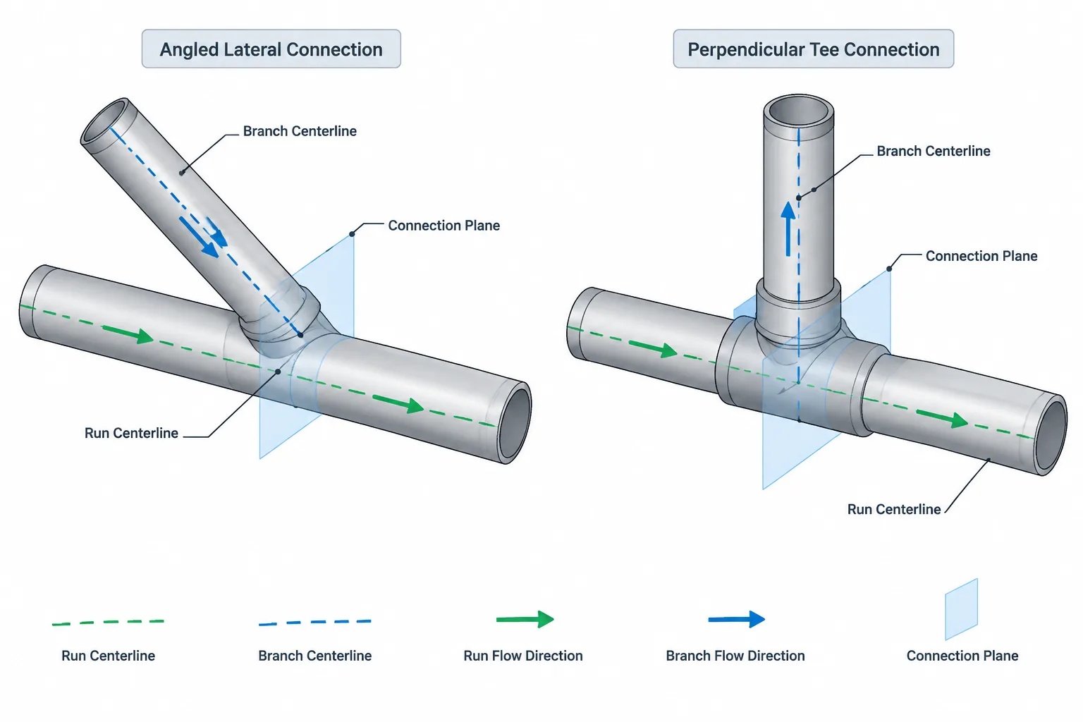
Choosing between a lateral pipe connection and a tee is not only a routing decision. Each arrangement establishes different centerline geometry, fitting endpoints, branch orientation, fabrication details, and documentation requirements. Those differences become especially important when a model is used for pipe cut lengths, interference review, material reporting, or isometric production.
This guide explains how laterals differ from conventional tees and how to control branch angle, clocking, takeoff, and component identity in piping CAD. It also highlights why an angled branch should be modeled from verified connection geometry rather than created by visually rotating pipe away from a tee.
A lateral pipe connection creates a branch that leaves the run at an oblique angle rather than at the right angle normally associated with a tee. This difference affects more than the appearance of the fitting. Branch angle influences routing, fitting takeoff, weld locations, pipe cut lengths, flow direction, reinforcement review, and the way the connection must be represented in a CAD model or fabrication drawing.
The word lateral is also used inconsistently. It may describe a manufactured fitting, a fabricated branch assembly, or simply the angled branch itself. Designers should therefore avoid treating the name as a complete specification. The connection type, angle, end preparation, dimensions, material, wall requirements, and governing piping specification must all be identified independently.
What Is a Lateral Pipe Connection?
A lateral connection is a branch arrangement in which the branch centerline intersects the run centerline at an angle other than the perpendicular relationship of a conventional tee. The branch may be formed by a one-piece fitting, fabricated from pipe sections, or produced with a branch outlet component designed for an angled installation.
In common piping usage, a lateral fitting often resembles a Y-shaped junction. However, terms such as lateral, lateral tee, wye, Y-branch, and angled branch do not always identify interchangeable products. Terminology varies among industries, manufacturers, and project specifications. The component description should be supported by verified dimensional and procurement information.
Lateral Connection vs. Standard Tee
| Characteristic | Lateral connection | Standard tee |
|---|---|---|
| Branch direction | Branch leaves the run at an oblique angle | Branch is normally perpendicular to the run |
| Centerline geometry | Requires an explicitly defined branch angle | Usually represented by orthogonal centerlines |
| Routing effect | Changes direction while creating the branch | Creates a branch without an inherent downstream diagonal |
| Dimension control | May require several center-to-end dimensions and angle control | Commonly controlled by run and outlet center-to-end dimensions |
| CAD placement | Requires correct angular orientation and rotation about the run | Requires branch clocking but usually no separate branch-angle input |
| Procurement description | Must clearly distinguish fitting type, angle, sizes, and ends | Typically identified by tee type, size combination, and ends |
A lateral should not be modeled as a tee with the branch pipe merely rotated. Rotating the branch alone does not reproduce the fitting body, intersection geometry, takeoff, or weld-end locations. It can also create incorrect pipe cut lengths and misleading interference results.
Branch Angle and Included-Angle Terminology
Angle descriptions can become ambiguous unless the drawing identifies the reference lines. One person may measure the acute angle between the branch and the forward run direction, while another may describe the supplementary angle relative to the opposite run direction. A text note without graphic context can therefore be misunderstood.
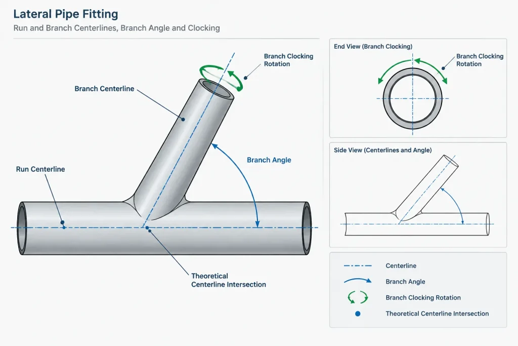
The most reliable drafting approach is to show the run and branch centerlines, mark the actual angle between the intended directions, and include flow arrows where flow direction is relevant. If the project uses a specific angle-naming convention, that convention should be applied consistently in models, drawings, material descriptions, and purchase data.
Branch angle and branch clocking are separate controls:
- Branch angle describes how far the branch departs from the run direction.
- Branch clocking describes rotation of the branch around the run centerline.
A lateral can point upward, downward, horizontally, or in a rolled direction while retaining the same branch angle. A correct 3D model must control both values.
Equal and Reducing Laterals
Like tees, lateral fittings may be described as equal or reducing. An equal lateral has a branch associated with the same nominal size as the run, while a reducing lateral has a smaller nominal branch. This terminology concerns nominal connection sizes, not actual bore continuity or flow area.
Size order must be stated according to the project or catalog convention. The written order alone should not be trusted when a component has multiple ends that could be interpreted differently. A component record should identify the two run ends and the branch end explicitly. A small orientation sketch can eliminate uncertainty in material requests and custom-part records.
Nominal size also does not define outside diameter, wall thickness, end preparation, or bore. Those properties must be obtained from the applicable component specification and verified dimensional source.
Manufactured Fitting vs. Fabricated Lateral
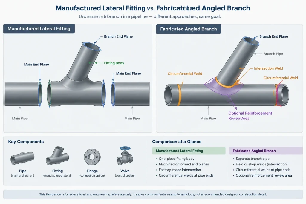
A manufactured lateral is supplied as a defined component with established end locations and product dimensions. A fabricated lateral may be created by cutting and joining pipe, sometimes with added reinforcement or a specially formed intersection. Although both arrangements can produce similar centerline paths, they are not automatically equivalent.
The distinction affects:
- Material identification and traceability
- Weld quantity and weld locations
- Branch reinforcement evaluation
- Inspection and examination requirements
- Dimensional tolerances
- Fabrication methods and shop capability
- Bore profile and internal flow path
CAD geometry should not imply that a fabricated branch is acceptable merely because the solids intersect cleanly. The piping design basis must establish whether a listed fitting, branch outlet, or engineered fabricated connection is required. Reinforcement adequacy and pressure design cannot be determined from the visual model alone.
Centerline Geometry and Takeoff
The useful geometric reference for layout is usually the theoretical intersection of the run and branch centerlines. Component dimensions then locate the physical ends relative to that reference. A lateral may have different takeoffs toward the run ends and branch end, so a generic symmetrical symbol should not be used for cut-length calculations unless symmetry has been verified.
To calculate adjoining pipe lengths, the designer should work from controlled endpoints and subtract the verified fitting takeoffs along the corresponding pipe centerlines. Measuring between visible solid faces can be unreliable because bevels, weld preparations, simplified model geometry, or display settings may move the selected point away from the intended dimensional reference.
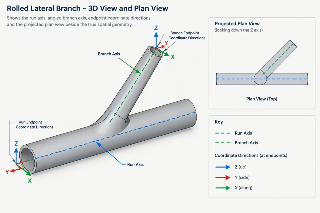
For a rolled lateral, coordinate differences must be evaluated in three dimensions. A plan-view angle does not necessarily represent the true branch angle. The model should be checked using centerline vectors or verified endpoint coordinates rather than a projected drawing view.
Flow and Layout Considerations
An angled branch may provide a more gradual change in flow direction than a perpendicular branch, but that observation is not a substitute for hydraulic analysis. Actual behavior depends on the fitting geometry, size relationship, flow direction, velocity, phase, and service conditions. A lateral used to combine streams may also behave differently from the same shape used to divide a stream.
From a layout perspective, a lateral can reduce the need for an immediate elbow and may create a smoother diagonal route. It can also consume more longitudinal space than a tee, move the branch weld farther from the intersection, and create a larger oblique envelope. Nearby steel, cable trays, equipment, insulation, and access zones should be checked using the full component and branch geometry.
A Practical CAD Modeling Workflow
- Confirm the component definition. Determine whether the design calls for a manufactured lateral, a fabricated branch, or another angled outlet arrangement.
- Verify the connection sizes. Identify both run ends and the branch end rather than relying on an unexplained size string.
- Obtain controlled dimensions. Use the applicable project-approved source for center-to-end dimensions, wall information, end preparations, and other required geometry.
- Establish the centerline intersection. Place the fitting from a stable insertion point tied to the run and branch axes.
- Set the branch angle. Confirm which run direction is used as the angular reference.
- Set branch clocking. Rotate the connection about the run axis to the required spatial orientation.
- Connect adjoining pipe at defined end planes. Do not trim pipe to an approximate visual intersection.
- Check coordinates and true lengths. Verify the branch endpoint in three dimensions, especially for rolled arrangements.
- Review clashes and fabrication access. Include insulation, weld access, examination access, and nearby structural elements where applicable.
- Synchronize documentation. Ensure the model, isometric, bill of material, and component description identify the same connection.
Drawing and Isometric Documentation
A piping isometric should make the angled relationship visually clear while providing enough dimensional control to reconstruct it. Depending on project practice, useful controls may include endpoint coordinates, centerline dimensions, elevations, branch angle, and fitting identification. The drawing should avoid combining redundant dimensions that create a closed and potentially conflicting dimension loop.
For a fabricated connection, drawings may also need to distinguish the intersection weld from nearby circumferential pipe welds. A single fitting symbol is not sufficient if the fabricator must develop cut profiles, locate reinforcement, or follow a special weld configuration. Those requirements belong in controlled fabrication details or referenced project documents rather than in an assumed generic CAD block.
Common Modeling and Documentation Errors
- Using a standard tee body and rotating only the branch pipe
- Confusing branch angle with rotation around the run
- Reading a projected plan angle as the true three-dimensional angle
- Assuming every product called a wye has the same dimensions or end arrangement
- Using nominal sizes to infer actual bore or wall thickness
- Mirroring an asymmetrical fitting without checking end designations
- Calculating cut lengths from graphic faces instead of controlled end planes
- Representing a fabricated intersection as a standard purchased fitting
- Omitting the angle from procurement or fabrication descriptions
- Assuming visually clean intersecting solids demonstrate acceptable reinforcement
What a Reusable CAD Component Should Contain
A controlled lateral component should include a clear insertion point, separate run and branch axes, defined connection planes, nominal end-size properties, and an unambiguous orientation convention. Useful metadata may also identify the component type, end connections, material or piping-class reference, dimensional source, and revision status.
Parametric behavior should be based on verified dimensional records rather than geometric scaling. Scaling one lateral model to represent another size changes every feature proportionally, while real component dimensions do not necessarily follow one uniform scale factor. Where dimensions are unavailable or project-specific, the model should be marked as preliminary rather than treated as fabrication-ready.
Key Takeaway
A lateral pipe connection is not simply a slanted tee. Its branch angle, clocking, end locations, component type, and dimensional basis must all be controlled. Clear centerline references and verified fitting dimensions allow the CAD model to support routing, cut-length calculations, material reporting, and fabrication documentation without implying design details that have not been confirmed.
Design Review and Model Handoff Checklist
Before releasing a lateral connection for design coordination, procurement, or fabrication, reviewers should confirm that the graphical model and component data describe the same physical arrangement. A correct-looking centerline path is not enough if the fitting body, end planes, or branch designation remain undefined.
- Connection identity: State whether the item is a manufactured fitting, a branch outlet arrangement, or a fabricated pipe intersection.
- End identification: Distinguish each run end from the branch end and confirm that size descriptions follow the approved convention.
- Angular reference: Show which run direction establishes the branch angle and keep that convention consistent across drawings and model properties.
- Spatial orientation: Verify branch clocking independently from branch angle, particularly where the connection is rolled out of a principal view.
- Dimensional basis: Associate takeoffs and connection planes with an approved dimensional source rather than scaled or visually estimated geometry.
- End conditions: Confirm that adjoining pipe connects at the intended end planes and that end preparation is represented or documented as required by the workflow.
- Component status: Mark conceptual or preliminary geometry clearly when procurement dimensions or project-specific details have not been confirmed.
- Document consistency: Compare the model, isometric, material description, fabrication detail, and any component metadata for conflicting terminology or orientation.
Why the Distinction Matters Across Disciplines
Piping layout personnel use the connection geometry to establish routing and clearances. Stress, hydraulic, materials, fabrication, inspection, and construction personnel may rely on different attributes of the same connection. Calling an item a lateral without defining its physical and specification requirements can therefore transfer unresolved assumptions between disciplines.
A useful CAD object should communicate what has been verified while avoiding implications about pressure design, reinforcement, or product availability that the model cannot establish. Where the final connection depends on engineering review or vendor information, the documentation should preserve that status rather than presenting generic geometry as a fully defined component.
Frequently Asked Questions
Is a lateral pipe connection the same as a tee?
No. A conventional tee normally has a perpendicular branch, while a lateral has an oblique branch relationship. The body geometry, end locations, takeoffs, and documentation requirements may also differ.
Can a tee model be edited to represent a lateral?
Rotating only the branch pipe does not create an accurate lateral. A usable model must represent the intended fitting or fabricated intersection, including its centerline relationship, connection planes, takeoffs, and component identity.
What is the difference between branch angle and branch clocking?
Branch angle describes the branch direction relative to the run. Branch clocking describes rotation around the run axis. Both must be controlled to locate an angled branch correctly in space.
Why can a plan view show the wrong branch angle?
A rolled branch is projected onto the drawing plane, so the apparent angle in that view may not equal the true angle between the pipe centerlines. Centerline vectors, controlled coordinates, or verified model geometry should be used for confirmation.
Does the term wye fully define a lateral fitting?
No. Terminology varies by industry, supplier, and project. The component description should independently identify the connection type, end sizes, angle convention, end preparation, material requirements, and dimensional source as applicable.
Can nominal pipe size be used to determine the lateral bore?
No. Nominal size identifies the connection in a standardized naming system but does not by itself establish the actual bore, wall thickness, outside diameter, or internal transition.
Does a clean CAD intersection prove that a fabricated lateral is acceptable?
No. Solid-model intersection quality does not establish pressure design, reinforcement adequacy, weld suitability, examination requirements, or compliance with the governing piping specification.
What should be checked before calculating pipe cut lengths?
Confirm the theoretical centerline intersection, verified fitting takeoffs, defined connection planes, end preparation references, and the true spatial direction of each adjoining pipe. Avoid measuring from convenient graphical faces unless those faces are confirmed dimensional references.