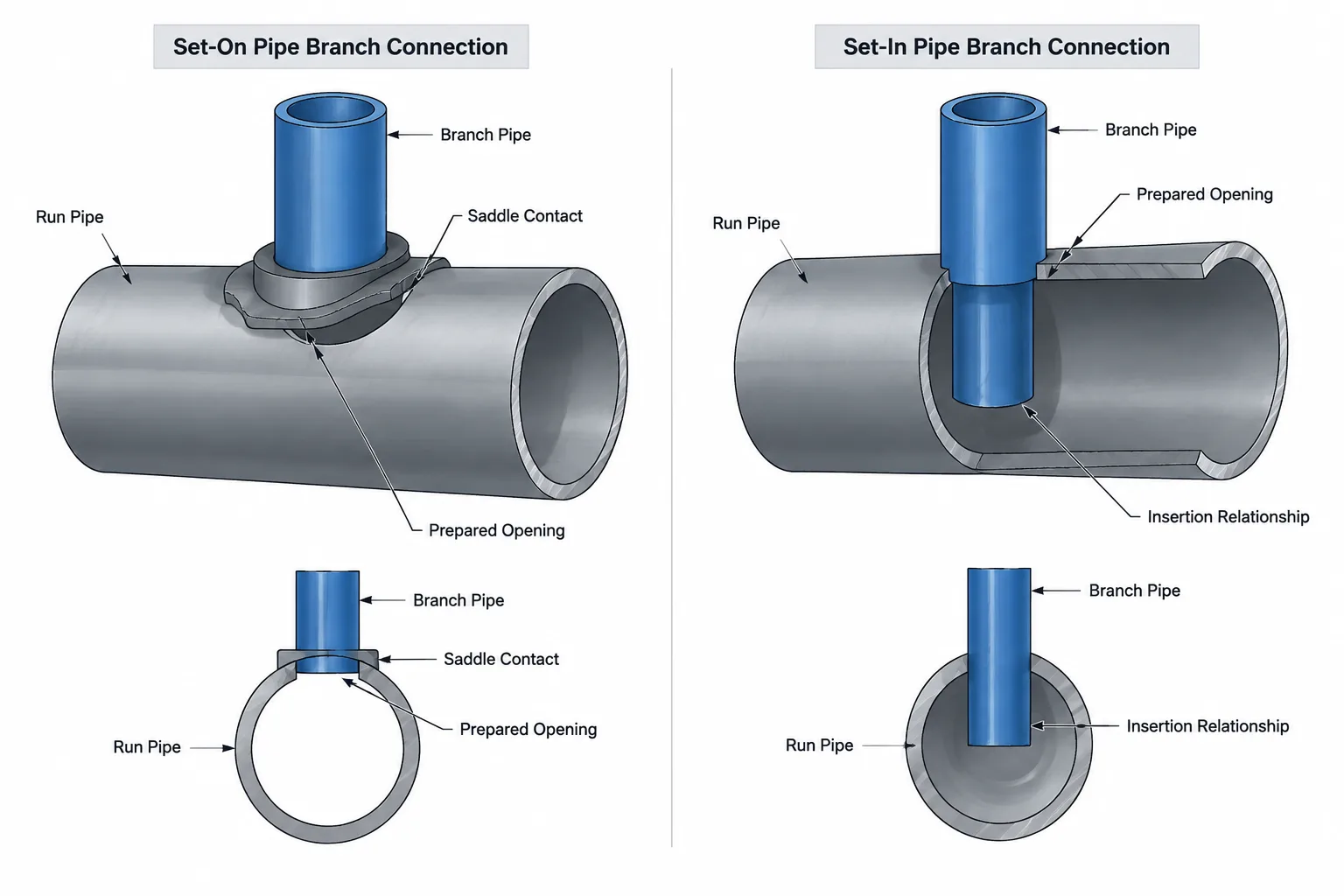
Set-on vs. set-in pipe branch connections describe different physical relationships between a fabricated branch, the run pipe, and the prepared opening. Although both arrangements may share the same piping centerlines, they require different assumptions about branch-end preparation, fit-up, cut-length references, and internal termination.
This guide explains how to recognize each arrangement and how to communicate the selected construction in CAD models, spool drawings, weld details, and fabrication documents. It is a terminology and documentation reference; final connection design, reinforcement, welding, and examination requirements must follow verified project engineering documents.
A fabricated pipe branch can look simple in a piping model: one centerline intersects another, and the branch size is assigned. In the fabrication shop, however, that intersection must become a defined opening, prepared pipe ends, welds, and possibly reinforcement. Two terms commonly used to describe this construction are set-on and set-in.
The distinction affects how the branch pipe meets the run pipe, how the opening is cut, and which surfaces form the weld joint. It may also affect branch cut length, fit-up, inspection access, reinforcement detailing, and the geometry shown on fabrication drawings. Because terminology can vary among companies and fabricators, a project should define the intended joint rather than relying on the name alone.
What is a fabricated branch connection?
A fabricated branch connection is produced by cutting an opening in a run pipe or header and welding a branch pipe directly to it. This differs from inserting a manufactured tee or a separate branch outlet fitting into the line.
The run pipe is often called the header, main, or run. The intersecting pipe is the branch. A fabricated intersection may be perpendicular or angled, and the branch may be equal to or smaller than the run. Its acceptability and required reinforcement depend on the applicable design rules, piping specification, service, materials, wall thicknesses, and calculated loads.
A CAD model showing two intersecting cylinders does not establish whether the connection is set-on or set-in. The model must either represent the selected construction or carry enough data for the fabrication drawing to define it.
What is a set-on branch?
In a typical set-on arrangement, the prepared end of the branch pipe fits against the outside surface of the run pipe. The end of the branch is contoured into a saddle shape so that it follows the curved exterior of the run. An opening is cut through the run wall to provide the flow path.
The branch is therefore positioned on the run rather than extending into the run opening. The intersection curve between the outside surfaces helps define the saddle cut, although the final preparation must also account for the specified weld joint.
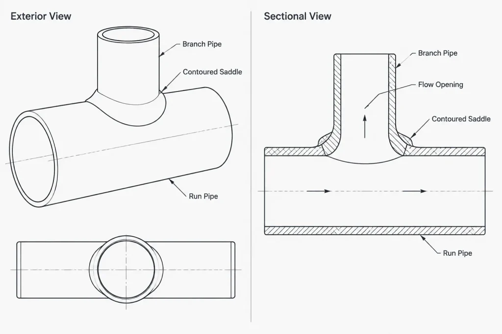
Practical characteristics of a set-on connection include:
- The branch end requires a contoured cut matching the run outside surface.
- The run opening is generally associated with the branch bore and required joint preparation, not simply the branch outside diameter.
- The outside toe of the branch provides a visible reference for locating the connection.
- The branch cut length is related to the outside surface of the run and the saddle profile.
- Any reinforcement pad or added reinforcement must be detailed as a separate feature when required.
The phrase set-on does not, by itself, define weld penetration, bevel geometry, reinforcement, examination, or acceptance criteria. Those details must come from the governing design and fabrication documents.
What is a set-in branch?
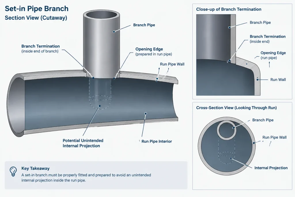
In a typical set-in arrangement, the branch end fits into an opening prepared in the run pipe. The opening accommodates the outside of the branch or the particular joint geometry specified for the connection. The branch end terminates within the run-wall region rather than resting entirely on the run’s exterior surface.
This changes the geometric relationship used for fit-up. The opening edge and branch wall form the joint, so opening size and preparation are closely linked to the branch outside diameter, wall thickness, bevel, and required weld configuration.
Practical characteristics of a set-in connection include:
- The run opening is prepared to receive the branch end.
- Branch insertion or penetration must be controlled rather than left as an accidental result of intersecting CAD solids.
- The internal profile should not create an unintended projection, restriction, or debris trap.
- The branch cut length depends on the defined termination surface and fit-up detail.
- The opening edge may require a more specific preparation than a simple circular cut.
Some organizations also use terms such as set-through for a branch that extends farther into or through the run. Definitions are not perfectly universal. A drawing should therefore show a section detail or reference a controlled project detail when the exact arrangement matters.
Set-on and set-in comparison
| Consideration | Set-on branch | Set-in branch |
|---|---|---|
| Basic position | Branch end fits against the run’s outside surface | Branch end fits into a prepared run opening |
| Branch-end shape | Usually a saddle contour matching the run exterior | Prepared to suit the opening and specified joint |
| Opening relationship | Opening provides the flow path below the seated branch | Opening also receives or locates the branch end |
| Cut-length reference | Often controlled to the run outside surface and saddle profile | Controlled to the specified insertion or termination geometry |
| CAD risk | Leaving overlapping solids without creating the saddle cut | Allowing an uncontrolled internal projection or incorrect opening |
| Drawing need | Identify the saddle, opening, joint, and reinforcement | Identify opening preparation, branch position, joint, and reinforcement |
Why centerline geometry is not enough
Routing software often creates a branch by connecting ports or intersecting centerlines. This is useful for system layout, but it may conceal the actual fabrication geometry. Several different constructions can occupy the same nominal centerline location:
- A manufactured tee
- A branch outlet fitting
- A set-on fabricated branch
- A set-in fabricated branch
- A reinforced fabricated branch
- A connection based on a separate project detail
These alternatives are not interchangeable simply because their centerlines match. They may have different material requirements, cut lengths, welds, reinforcement, inspection needs, and procurement classifications.
Designers should assign an explicit component or connection type in the model database where the software permits it. If the model uses simplified geometry, the isometric, spool drawing, weld detail, or fabrication note should carry the missing definition.
Branch cut length and reference surfaces
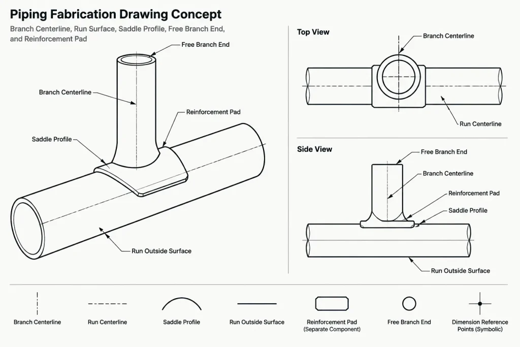
Branch cut length is a common source of error. A dimension from the branch centerline intersection to the free end does not necessarily describe the physical pipe piece. The actual end varies around the saddle or intersection profile.
Useful fabrication documentation distinguishes among:
- The theoretical intersection of the run and branch centerlines
- The run outside surface
- The shortest and longest points of a contoured branch end
- The branch end plane before contouring, when relevant to shop preparation
- The final free-end or connecting-face location
A single ambiguous length can lead the shop to measure from a different point than the designer intended. A section view, developed cutting profile, or controlled fabrication detail is often clearer than adding more dimensions to the piping plan.
Reinforcement is a separate design question
Set-on and set-in describe how the branch meets the run; they do not determine whether the connection is adequately reinforced. Reinforcement may come from available material in the run and branch walls, an added pad, an integrally reinforced fitting, or another engineered configuration.
Do not assume that a reinforcement pad is always required, or that adding one automatically makes a branch acceptable. The required arrangement depends on the applicable code calculation, project specification, geometry, material, service, corrosion allowances, loads, and fabrication details.
When a pad is required, the CAD and drawing package should distinguish it from the branch pipe. Its shape, material identification, weld boundaries, any required vent or test feature, and relationship to nearby seams or welds should be established by verified project documentation.
Recommended CAD and drawing workflow
1. Confirm the connection definition
Check the piping class, branch table, engineering detail, or approved fabrication practice. If the document says only “fabricated branch,” clarify whether the project distinguishes set-on from set-in construction.
2. Model the correct functional envelope
At minimum, represent the run, branch outside diameter, and any reinforcement that affects clearance. Higher-detail fabrication models should include the opening, saddle or insertion geometry, and defined internal termination.
3. Preserve centerline control
Locate the branch using coordinates, orientation, and centerline relationships. Do not let detailed trimming operations shift the intended branch location or angle.
4. Define the joint outside the solid model when necessary
If the model cannot reliably represent weld preparation, use a section detail or a referenced project detail. Avoid treating a Boolean cut as a complete weld specification.
5. Check the bill of material and weld data
A fabricated branch may not appear as a purchased fitting, but it still requires correct reporting of pipe pieces, reinforcement components, and welds. Confirm that automated extraction does not accidentally classify it as a tee or outlet fitting.
6. Review internal and external geometry
Check for unintended bore intrusion, excessive opening, inaccessible weld regions, interference with longitudinal seams, nearby fittings, insulation, supports, or adjacent branches. These checks should be coordinated with the responsible engineering and fabrication disciplines.
Documentation checklist
- Is the branch construction explicitly identified?
- Are run size, branch size, material, and wall designation controlled by verified project data?
- Is the branch angle and orientation unambiguous?
- Is the opening or saddle geometry defined at the appropriate drawing level?
- Is the branch cut-length reference clear?
- Are weld type and preparation controlled by an approved detail?
- Is required reinforcement shown and separately identified?
- Does the model avoid an unintended internal projection?
- Are BOM, weld map, spool drawing, and model classifications consistent?
Key takeaway
The practical difference between set-on and set-in branch connections is not merely naming. It is the physical relationship between the branch end, the run outside surface, and the prepared opening. That relationship influences cutting, fit-up, cut length, weld detailing, and model accuracy.
Because usage varies, the safest documentation combines a clear connection label with a controlled section detail or fabrication reference. Centerline intersections establish routing intent; they do not replace a defined branch joint.
Using the comparison during design review
A useful review begins by separating routing intent from fabrication intent. The routing model establishes where the branch is located and how it is oriented. The fabrication definition establishes how the branch end meets the run, how the opening is prepared, and where the finished pipe surfaces terminate.
When the construction cannot be determined from the model or drawing, reviewers should not infer it from intersecting centerlines or overlapping solids. The uncertainty should be resolved against the piping class, branch connection rules, approved detail, weld documentation, and shop practice before cut lengths or material reports are released.
Information to coordinate across deliverables
- Model data: Connection type, branch orientation, component classification, and reinforcement status should be consistent with the intended construction.
- Fabrication drawing: A section or controlled detail should identify the branch termination, opening relationship, and relevant cut-length reference.
- Bill of material: Pipe pieces and separate reinforcement items should not be replaced by an incorrect purchased-fitting classification.
- Weld documentation: Weld identity and joint preparation should come from approved fabrication information rather than the appearance of a CAD Boolean operation.
- Review record: Any terminology specific to the project or fabricator should be documented so later revisions use the same interpretation.
Avoiding terminology-driven errors
The labels set-on and set-in are helpful only when all parties apply the same definitions. A small section sketch showing the run wall, opening edge, branch wall, and intended termination can communicate more reliably than a connection name by itself.
If the shop, designer, and engineering documents use different terms, the physical geometry should govern the clarification. Resolve what is cut, what fits against or into the run, what projects into the bore, and which detail controls the weld. This approach reduces ambiguity without treating informal terminology as a substitute for an approved design.
Frequently asked questions
Can set-on and set-in branches have the same centerline location?
Yes. The run and branch centerlines can occupy the same model location while the end preparation, opening, insertion, and weld-joint geometry differ. Centerline agreement does not establish the fabrication method.
Does a set-on connection mean the opening matches the branch outside surface?
Not necessarily. In a set-on arrangement, the branch seats against the run exterior, while the opening provides the flow path and supports the specified joint geometry. The required opening should be taken from approved fabrication information rather than assumed from the visible branch envelope.
Should a set-in branch project into the run bore?
The intended termination must be defined and controlled. An internal projection should not be accepted merely because intersecting CAD solids created it. The model or fabrication detail should show the approved relationship between the branch end and the run interior.
Does either branch type automatically require a reinforcement pad?
No. The connection name does not determine reinforcement adequacy. Reinforcement must be established from the applicable design evaluation, piping specification, materials, geometry, service conditions, loads, and approved project details.
Is a Boolean intersection sufficient for a fabrication drawing?
No. A Boolean operation may depict an opening or trimmed solid, but it does not define weld preparation, fit-up allowance, reinforcement, examination, or acceptance requirements. Those items need controlled engineering and fabrication documentation.
What should be clarified when the drawing says only fabricated branch?
Clarify whether the branch rests on the run exterior or fits into the opening, how the branch end and opening are prepared, where cut length is measured, whether reinforcement is required, and which approved weld detail applies.