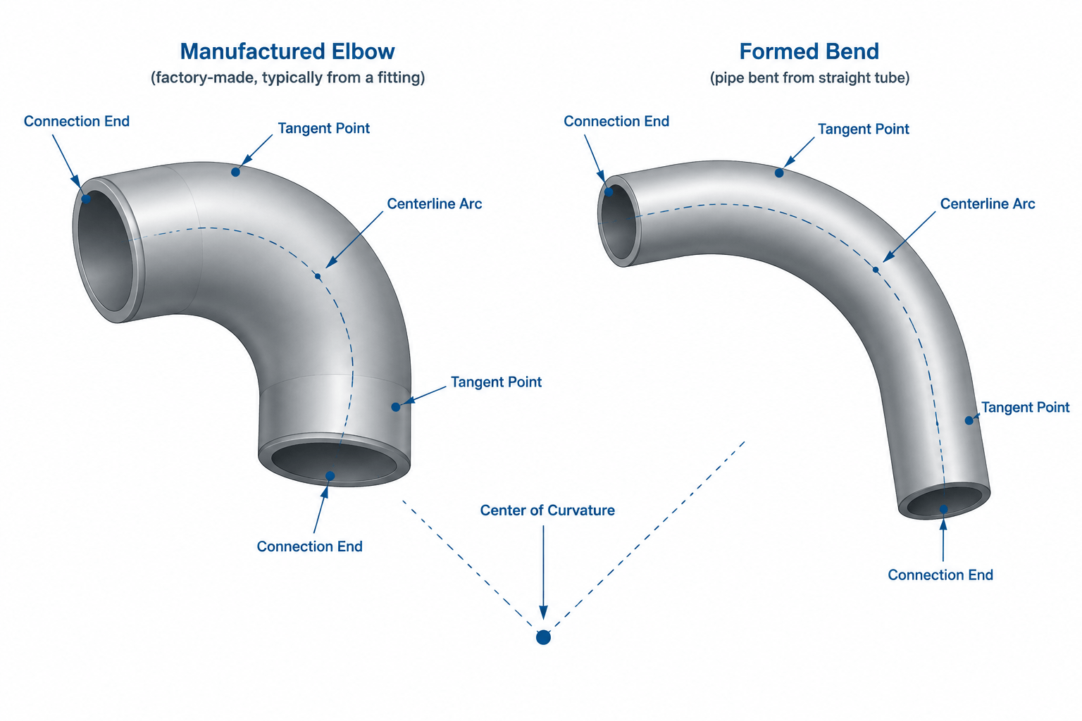
Pipe bends and elbows may create similar changes in route direction, but they represent different physical products and require different CAD controls. Correct identification affects connection locations, centerline geometry, fitting attributes, fabrication instructions, isometric output, and material reporting.
This guide explains how to distinguish a manufactured elbow from formed pipe, define bend geometry with tangent points, and keep the model consistent with drawings, schedules, and bills of material. Project-approved piping specifications, component databases, and fabrication requirements remain the controlling sources for dimensional data.
Pipe bends and elbows can change a piping route in the same general direction, but they are not interchangeable drafting terms. An elbow is typically a manufactured fitting with standardized or manufacturer-defined dimensions. A pipe bend is formed from pipe, with its geometry described by bend radius, angle, and tangent locations. That distinction affects CAD modeling, dimensioning, material takeoff, fabrication data, and design review.
A centerline route may look correct while still representing the wrong component. For example, replacing a specified elbow with a generic centerline arc can change connection points and omit fitting data. Conversely, inserting an elbow block where a formed bend is intended may create unnecessary joints and an inaccurate bill of materials. The goal is not merely to draw a turn; it is to document how that turn will be made.
What Is the Difference Between a Pipe Bend and an Elbow?
An elbow is a discrete piping component. It has defined ends, a nominal angle, a center-to-end or center-to-face dimension, and an applicable end connection such as butt weld, socket weld, threaded, or flanged. Its dimensions should come from the project-approved component reference, piping specification, or verified local database.
A pipe bend is a curved portion of pipe produced by a bending process. It is usually described using a centerline bend radius, bend angle, tangent points, and straight lengths at one or both ends. Depending on the fabrication method, the bend may be made in the same pipe length as adjacent straight runs rather than installed as a separate fitting.
| Characteristic | Elbow | Pipe bend |
|---|---|---|
| Basic identity | Separate manufactured fitting | Formed section of pipe |
| Primary dimensional source | Verified fitting table or manufacturer data | Approved bend radius, angle, and fabrication requirements |
| Route control | Fitting center and connection ends | Tangent points and centerline arc |
| Typical material listing | Individual fitting item | May be identified as bent pipe or a fabricated bend item |
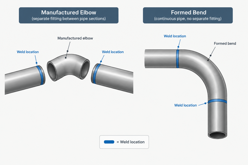
| Joint implications | Often introduces connections at both ends | May reduce or relocate joints, depending on fabrication |
| CAD risk | Using an unverified generic fitting size | Drawing an arc without defining radius or tangency |
Terminology is not perfectly uniform across every industry or supplier. Some catalogs use the word bend for manufactured fittings, while some projects classify certain curved components separately from field- or shop-bent pipe. The piping material specification and project component descriptions should control the final designation.
Geometry Terms That Control a Pipe Bend
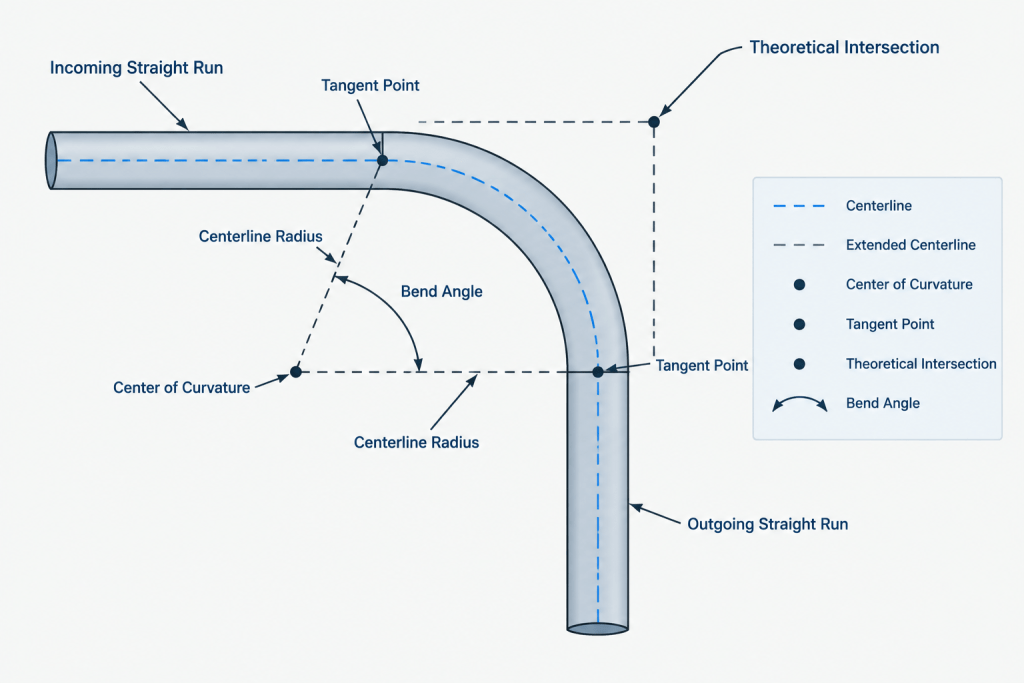
Centerline bend radius
The centerline bend radius is measured from the center of curvature to the pipe centerline. It is not normally measured to the inside or outside surface unless the documentation says otherwise. A CAD model should store or clearly communicate which radius convention is being used.
Do not infer a bend radius from appearance. A smooth arc in a schematic view may only indicate a directional change. The actual radius must come from approved design or fabrication information.
Tangent points
A tangent point is where the straight pipe centerline transitions into the circular bend centerline. A simple bend has an incoming tangent point and an outgoing tangent point. These points are important because they define the curved portion independently of any extra straight pipe left for gripping, welding, trimming, or field adjustment.
Dimensions to an imaginary intersection of the straight centerlines are not the same as dimensions to the tangent points. A drawing that mixes these references can shift adjacent welds, supports, nozzles, or branch locations.
Bend angle
The bend angle is the directional change between the incoming and outgoing straight centerlines. CAD software may represent that angle using an included angle, deflection angle, or arc sweep. Confirm which value the software reports before copying it into a bend schedule.
For a circular centerline arc, its developed centerline length can be calculated as L = Rθ, where R is the centerline radius and θ is the sweep angle expressed in radians. This geometric result does not account for fabrication effects, trimming allowances, or process-specific requirements.
Straight tangent lengths
Fabrication may require straight pipe beyond the theoretical tangent points. These straight portions are not part of the bend arc, but they can affect the purchased length, spool envelope, and connection location. Show whether a listed length is arc only, tangent-to-tangent, end-to-end, or an overall blank length.
How Elbow Geometry Is Controlled
An elbow should normally be modeled from verified fitting dimensions rather than reconstructed from an assumed radius. The most useful placement references are its connection points, fitting center, nominal angle, and applicable center-to-end dimensions. Reducing elbows and special-angle elbows may require additional dimensional data because their ends are not necessarily symmetric.
A nominal elbow angle does not by itself define every dimensional property. Fitting type, size, schedule or wall designation, end preparation, and manufacturing standard can affect the selected CAD component. Use authoritative reference tables for numeric geometry and treat the model symbol as a representation of that specific catalog or specification item.
A Practical CAD Modeling Workflow
- Confirm component intent. Determine whether the route calls for a manufactured elbow, formed pipe bend, or supplier-specific curved component. Do not decide from the graphics alone.
- Establish route centerlines. Model the incoming and outgoing straight centerlines with the required direction and elevation. Keep their theoretical intersection available as construction geometry if it helps with checking.
- Apply verified geometry. For an elbow, insert the approved component using database dimensions. For a bend, enter the approved centerline radius and angle rather than drawing a visually convenient arc.
- Mark tangent points for bends. Use geometric constraints so the arc is tangent to both straight centerlines. Unconstrained arcs can create small direction changes that are difficult to see but problematic for fabrication data.
- Preserve connection metadata. Elbows should retain end type, specification, size, wall or schedule designation, and item identity. Bends should retain radius, angle, bending method if required by the project, and any fabrication notes.
- Check adjacent features. Confirm that branches, supports, welds, insulation breaks, and equipment connections are referenced from unambiguous locations. Avoid locating them from a decorative arc endpoint or approximate fitting outline.
- Generate and review output. Compare the model, isometric, bend schedule, and material list. A component that appears correctly in 3D can still be classified incorrectly in reports.
Dimensioning Bends Without Ambiguity
A useful bend detail identifies enough information to reproduce the intended centerline geometry. Depending on project practice, that may include the bend angle, centerline radius, tangent points, endpoint coordinates, plane of bend, and straight lengths.
- State that the radius is a centerline radius when there is any chance of confusion.
- Differentiate tangent-to-tangent dimensions from end-to-end dimensions.
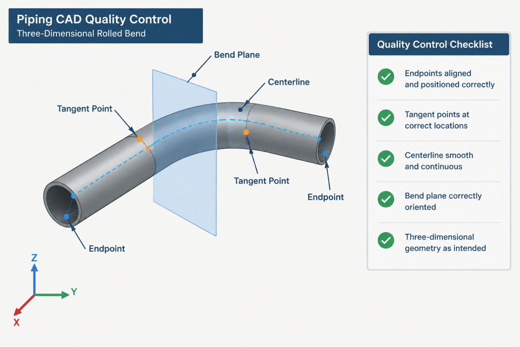
- Use coordinates or controlled dimensions to locate bend endpoints in three-dimensional routing.
- Identify the bend plane or orientation when the bend is not confined to an obvious plan or elevation plane.
- Avoid dimensioning only to the apparent outside edge of the pipe.
- Keep fabrication allowances separate from finished design geometry.
A rolled or spatial bend needs particular attention. Two endpoint coordinates and one radius may not fully establish its orientation. The model or drawing should also communicate the bend plane, normal direction, or another reliable orientation reference.
Bill of Material and Isometric Treatment
An elbow is generally counted as a fitting because it is installed between adjacent piping elements. Its description should match the piping specification and the geometry used in the model. If the CAD library contains several visually similar elbows, confirm that the selected record carries the correct attributes rather than relying on block appearance.
A formed bend may be handled as part of a pipe item, as a separately identified fabricated component, or through a bend schedule. The correct method depends on the project’s procurement and fabrication workflow. What matters is that the drawing and material output agree. A bend shown graphically but reported as a standard elbow can cause purchasing and spool-planning errors.
On an isometric, use the project’s established symbol convention, but supplement the symbol with data where needed. Radius, angle, bend identification, tangent references, and spool assignment are more useful to fabrication than a smooth curve with no definition.
Common Modeling and Review Errors
- Replacing database elbows with arbitrary arcs: This can change takeoff dimensions and remove component attributes.
- Calling every directional change an elbow: The wording may conflict with the fabrication method and material list.
- Using outside radius as centerline radius: The resulting path and developed length will be incorrect.
- Locating welds at tangent points automatically: A tangent point is a geometric transition, not necessarily a physical joint.
- Ignoring straight end requirements: The finished bend may need more pipe than the centerline arc alone suggests.
- Approximating special angles with standard-angle graphics: The displayed symbol and actual route data may disagree.
- Losing bend orientation during isometric extraction: A three-dimensional bend can appear plausible while being rotated into the wrong plane.
Review Checklist
- Is the directional change identified as the intended component type?
- Do elbow dimensions come from a verified reference source?
- Is the pipe bend radius measured to the centerline and explicitly understood?
- Are both tangent points geometrically constrained?
- Are angle and bend-plane conventions clear?
- Do finished endpoints match the required coordinates or controlled dimensions?
- Are weld locations independent of theoretical tangent points unless intentionally coincident?
- Does the bill of materials classify elbows and bends consistently with the model?
- Are fabrication allowances separated from final installed geometry?
- Do the model, isometric, and bend schedule describe the same route?
The key drafting principle is to model the physical product, not just the shape of the centerline. Use verified dimensional tables for manufactured elbows and explicit radius-and-tangent geometry for formed bends. That distinction keeps routing, fabrication documents, and material data aligned without attempting to replace the project’s authoritative component references.
Separate Route Geometry From Component Identity
A useful CAD review treats the directional change as both a geometric object and a physical piping item. The geometric layer establishes the centerline path, endpoints, direction, and orientation. The component layer establishes whether the turn is an elbow, a formed bend, or another approved curved component.
Matching only the centerline shape is not enough. An elbow can appear correct while carrying the wrong fitting record, and a bend can appear smooth while lacking controlled tangency or fabrication information. Both layers must agree before the route can be considered properly documented.
- For elbows: Verify the component identity, connection definitions, approved dimensions, and material attributes.
- For bends: Verify the centerline radius convention, bend angle, tangent locations, orientation, and required straight portions.
- For drawings: Confirm that dimensions reference intentional geometric or physical points rather than approximate graphics.
- For reports: Confirm that the item classification agrees with the modeled fabrication method.
Resolve Discrepancies by Reference Type
When the model, isometric, and material report disagree, first identify what kind of reference is in conflict. A coordinate discrepancy concerns route location. A tangent discrepancy concerns where straight pipe transitions into curvature. A connection discrepancy concerns the physical ends of a component. A classification discrepancy concerns how the item is described and counted.
This distinction helps reviewers avoid correcting the visible shape while leaving the underlying object data wrong. The final check should compare geometry, component attributes, drawing annotations, fabrication output, and material reporting against the same approved project basis.
Frequently Asked Questions
Can an elbow be represented by a centerline arc in CAD?
A centerline arc may be part of its graphical representation, but it should not replace the verified elbow definition. The modeled item must retain the approved connection locations, fitting dimensions, end information, and component attributes.
Is a pipe bend tangent point also a weld location?
Not necessarily. A tangent point marks the geometric transition between straight and curved centerline segments. A weld is a physical connection and should be located from the fabrication or spool definition rather than assumed to coincide with tangency.
What information should define a formed pipe bend?
The documentation should identify the approved centerline radius, bend angle, tangent references, endpoint or route controls, and bend orientation. Straight end requirements and fabrication notes should also be included when required by the project workflow.
Why can a correct-looking model produce an incorrect bill of materials?
Material output usually depends on object identity and attributes, not appearance alone. A generic arc may not report as a fitting or fabricated bend, while an elbow object used in place of formed pipe may create an unintended fitting item and associated connections.
Can bend radius be estimated from a schematic or isometric?
No. Schematic curves and isometric symbols may communicate route direction without defining actual radius. Use approved design information, fabrication data, or the controlled model value.
How should a bend outside an obvious plan or elevation be documented?
Provide an unambiguous orientation reference in addition to the required endpoints and bend geometry. The bend plane, normal direction, coordinates, or another project-approved control should prevent the bend from being rotated into the wrong spatial orientation.