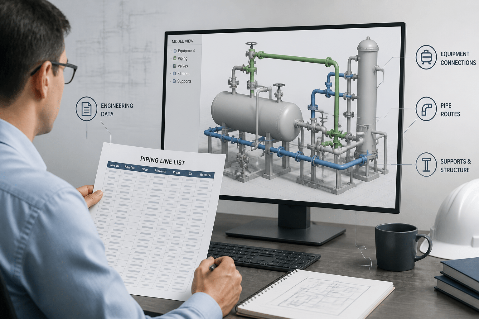
Before a piping line becomes CAD geometry, its identity and engineering context must be understood. A line list provides the first structured view of that information, but it is most useful when read together with the P&ID, piping material specification, equipment data, and current project revisions.
This guide explains how to read a piping line list as a modeling and coordination document. It focuses on the fields that influence CAD scope, connectivity, component selection, clearances, annotations, and review status—without treating the line list as a substitute for approved design documents.
A piping line list is one of the most useful control documents in a piping project. It provides a structured summary of each piping line and connects process information with materials, design conditions, insulation, tracing, testing, and drafting requirements. For a CAD designer, the line list is not simply a schedule of line numbers. It is a source of modeling inputs and a quality-control reference.
The exact fields vary by company and project. Some line lists are maintained in spreadsheets, while others are managed in engineering databases or plant design systems. The important skill is knowing what each field means, which fields affect the model, and which items must be confirmed before geometry is created.
What a piping line list does
A line list identifies piping segments that share a common set of process and engineering attributes. It commonly links a line number to information such as:
- Process service or fluid description
- Nominal pipe size
- Piping material specification
- Design pressure and design temperature
- Operating pressure and operating temperature
- Insulation, heat tracing, or personnel-protection requirements
- Fluid phase, hazardous-area information, or special handling notes
- Origin and destination equipment, vessels, headers, or battery limits
- Testing, cleaning, flushing, or other project-specific requirements
These fields do not all define physical geometry. Some describe process conditions, some control component selection, and others affect drafting, model coordination, or construction documentation.
Line list fields that matter most in CAD
Line number and segment identity
The line number is the primary identifier used to connect the line list with P&IDs, piping specifications, models, isometrics, and other project documents. A line number may represent a complete process connection between two points, or it may be divided into segments when the specification, size, temperature, or other controlling condition changes.
Do not assume that similar-looking line numbers are interchangeable. A suffix, segment code, or revision marker may carry important information. Before modeling, confirm the project convention for line breaks and the exact identifier that must appear on drawings.
Nominal size and piping specification
Nominal size establishes the general pipe size used for the line. The piping material specification controls the allowable component families and connection types for that line. It may determine the pipe wall designation, flange type, valve materials, gasket category, bolting, branch fittings, and other details.
For CAD work, size and specification should be treated as related but separate inputs. Two lines can have the same nominal size while using different component dimensions or connection details because they belong to different specifications. Conversely, a line can change size through a reducer while remaining within the same broader service route.
Use the project’s authoritative dimension and component data when creating geometry. The line list helps identify the required specification; it does not replace the project component library or approved reference tables.
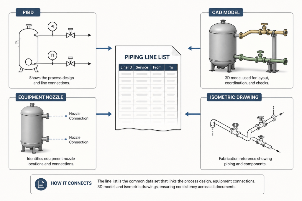
Origin and destination
Origin and destination fields describe the intended connectivity of the line. They may reference equipment nozzles, headers, another line, a utility connection, or a battery limit. These fields are valuable during the initial routing review because they provide a logical connection independent of the eventual physical route.
Check whether the listed origin and destination are process descriptions or exact nozzle identifiers. A general description such as a vessel outlet may require additional confirmation before it can be used for CAD modeling. The equipment arrangement, nozzle schedule, P&ID, and model data may be needed to establish the actual connection point.
Operating and design conditions
Operating conditions describe the expected normal service. Design conditions represent the basis used for engineering and component selection. Both can affect insulation, material selection, valve arrangement, supports, testing, and review requirements.
These values should not be silently converted into drawing geometry or used to make an independent suitability judgment. Instead, use them as review attributes and confirm that the line’s specification and project design basis are consistent. If a line list value conflicts with the P&ID, process data, or approved specification, stop and resolve the discrepancy through the project change process.
Insulation, tracing, and protective requirements
Insulation and tracing fields can affect clearances, support interfaces, access, and the appearance of plans and isometrics. A line may require thermal insulation, personnel protection, frost protection, process-temperature maintenance, or no insulation at all.
Look beyond the insulation abbreviation. Confirm the project’s meaning for thickness, removable sections, valve and flange boxes, tracing, and insulation breaks. These requirements can affect the modeled outside envelope even when the pipe centerline remains unchanged.
How to use a line list during the CAD workflow
1. Establish the line register
Begin by filtering the line list to the area, unit, or drawing package being developed. Check for duplicate identifiers, missing revisions, incomplete destinations, and lines marked as cancelled, preliminary, or superseded.
Create a working register that records the line identifier, source document revision, specification, size, origin, destination, and current modeling status. This register helps prevent a line from being modeled twice or omitted from the drawing package.
2. Compare the line list with the P&ID
Use the P&ID to verify process connectivity, valves, branches, drains, vents, instruments, and flow-direction requirements. The line list may summarize a line, but it normally does not show every inline or off-line component.

Pay particular attention to lines that split, join, change size, change specification, or connect to equipment through a special nozzle arrangement. These conditions often require multiple line-list entries or additional engineering documents.
3. Confirm model-driving attributes
Before drawing, identify which fields must become CAD properties or annotations. Typical model-driving attributes include:
| Line-list information | Typical CAD or review use |
|---|---|
| Line identifier | Tags, drawing references, model search, and document consistency |
| Size and specification | Pipe and component selection from the approved library |
| Origin and destination | Connectivity checks and routing scope |
| Insulation or tracing | Envelope, clearance, support, and annotation review |
| Design conditions | Engineering verification and controlled design-basis checks |
| Testing or special notes | Construction, inspection, and document coordination |
4. Record uncertainty instead of guessing
A missing field is not permission to choose a convenient value. Mark unresolved information clearly and identify the document or discipline that must provide the answer. Common examples include an unconfirmed equipment nozzle, an unclear specification break, an incomplete insulation note, or a destination that does not match the P&ID.
Temporary CAD geometry may be useful for coordination, but it should be visibly identified as preliminary and should not be allowed to appear as approved design information.
Common line-list mistakes
- Using the line number as the only source of truth: The identifier does not describe every valve, branch, reducer, or support requirement.
- Ignoring revisions: A current line list can differ from an older P&ID or model extract.
- Treating specification as a material description only: A specification can control connection details and component selection as well as material family.
- Modeling from a spreadsheet without checking units and conventions: Confirm how size, temperature, pressure, insulation, and status fields are defined in the project.
- Missing line segmentation: A change in size, material specification, service condition, or project boundary may require a separate line segment.
- Failing to propagate data: A correct line list entry is less useful if the line number or specification is missing from the model, isometric, or drawing annotations.
A practical review checklist
Before releasing a CAD deliverable, verify that each modeled line has a traceable line-list entry and that the entry is current. Then check:
- The line identifier agrees across the line list, P&ID, model, and drawing.
- Origin and destination are logically connected and match the assigned scope.
- Size and piping specification match the selected pipe and components.
- Specification or size changes are shown at the correct locations.
- Insulation, tracing, and special-service notes are represented or flagged for review.
- Unresolved data is documented rather than hidden in the model.
- Any change made during routing is communicated back to the controlling project documents.
Why the line list matters beyond drafting
A well-controlled line list creates a common language between process engineering, piping design, procurement, construction, and document control. For CAD teams, its greatest value is traceability: every modeled line should have a clear reason for its size, specification, destination, and special requirements.
Used properly, the line list becomes both a modeling input and a review tool. It helps the designer understand the scope before routing begins, exposes missing information early, and makes it easier to verify that the final CAD deliverable still represents the approved engineering intent.
How to organize line-list information before modeling
A practical way to begin is to separate line-list fields into three groups: identity, geometry-related inputs, and review or construction attributes. Identity fields establish which line is being modeled. Geometry-related inputs help define the route and component data to be retrieved. Review attributes provide conditions or requirements that must remain visible to the design and checking teams.
This separation helps prevent a common drafting error: treating every spreadsheet field as if it directly creates geometry. Some entries control model properties or annotations, while others require confirmation from process, mechanical, materials, or construction documentation.
Build a traceability chain
For each line in the modeling scope, maintain a clear relationship between the line-list record, the applicable P&ID, the piping specification, the connected equipment or boundary, and the resulting CAD objects. This traceability makes later checking easier and helps explain why a route, component family, or annotation was selected.
When a source document changes, the traceability chain also identifies what needs to be reviewed. A revision may affect connectivity, line segmentation, component selection, insulation representation, or drawing notes even when the route appears visually unchanged.
Use status deliberately
Model status should communicate whether information is confirmed, under review, or awaiting input. A provisional route can support coordination, but its status should remain obvious in the model and related drawings. This is especially important when unresolved line-list data could affect nozzle connections, specification boundaries, or the modeled outside envelope.
Clear status communication is more reliable than relying on memory or informal comments. It gives reviewers a direct way to distinguish approved information from temporary coordination geometry.
Frequently asked questions
Is a piping line list enough to create a complete CAD model?
No. The line list provides important identity, process, specification, and coordination inputs, but it normally does not show every valve, branch, instrument, support, nozzle detail, or routing constraint. Confirm the model against the P&ID, approved component data, equipment information, and other controlling project documents.
Why should the line list be checked against the P&ID?
The line list summarizes a line, while the P&ID shows process connectivity and many of the components and branches that affect the modeled arrangement. Comparing the documents helps identify missing segments, unexpected branches, changed destinations, and revision mismatches before drafting progresses.
What should a CAD designer do when a line-list field is blank?
Do not fill the field with an assumption that could be mistaken for approved information. Record the missing input, identify the responsible document or discipline, and mark any temporary geometry as preliminary until the issue is resolved.
Can two lines with the same nominal size use different CAD components?
Yes. The piping material specification and project component library may lead to different pipe, flange, valve, gasket, bolting, or branch-fitting selections even when nominal size is the same. Size and specification must therefore be checked as separate modeling inputs.
How do insulation and tracing affect CAD review?
They can affect the modeled or reviewed outside envelope, clearances, access, supports, removable sections, and drawing annotations. Confirm the project conventions for representing these requirements instead of relying only on an abbreviation in the line list.
What is the best way to handle a line-list revision during modeling?
Compare the revised record with the current P&ID, specification, model data, and drawing package. Determine whether the change affects identity, connectivity, segmentation, component selection, or review notes, then communicate the required updates through the project change-control process.