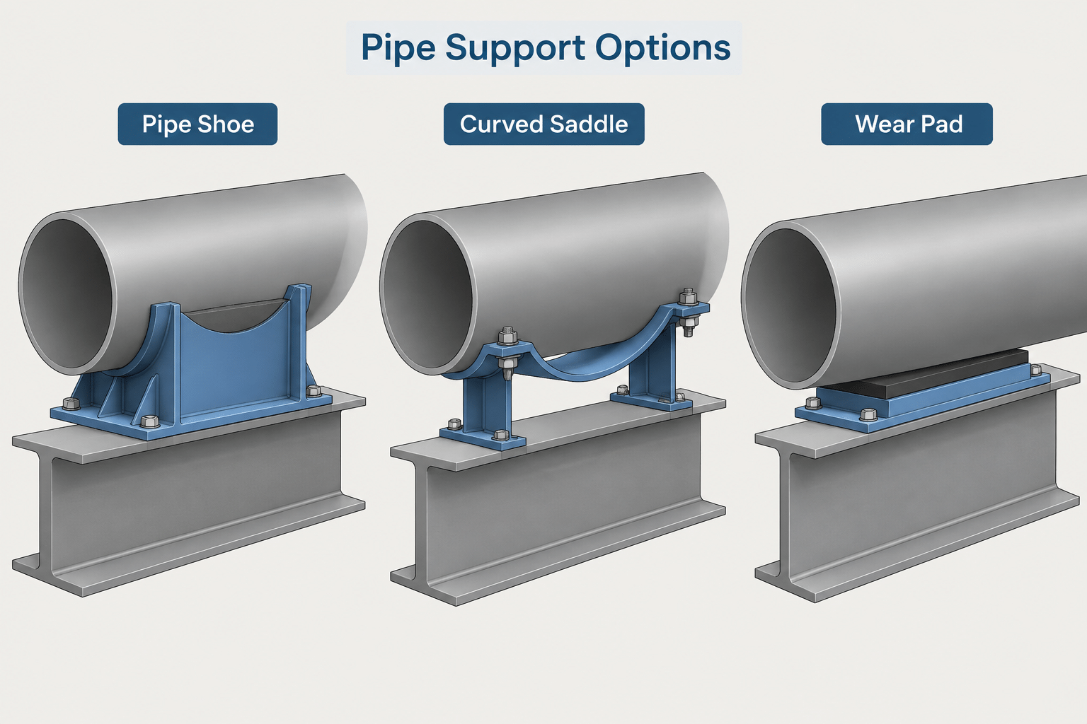
Pipe support geometry must communicate more than the visible shape beneath a line. In a CAD model, a pipe shoe, saddle, or wear pad should indicate where contact occurs, how load reaches the supporting structure, and which separate components control movement.
This guide explains how to distinguish these components and document their interfaces without treating generic library geometry as an approved support design. Use it when developing piping layouts, reviewing support models, coordinating with structural steel, or preparing details for engineering review.
Pipe shoes, saddles, and wear pads are often grouped under the broad label of “pipe supports,” but they do not perform identical functions. A shoe establishes a load-transfer and movement interface between the pipe and supporting structure. A saddle distributes contact around part of the pipe circumference. A wear pad primarily protects or reinforces a local area and may be only one part of a complete support assembly.
These distinctions matter in CAD. A simplified support symbol may be sufficient for an early routing study, while a fabrication or construction detail may need to show attachment limits, insulation treatment, sliding surfaces, structural steel, weld extent, and the party responsible for each component. Accurate geometry alone is not enough if the drawing leaves the support function unclear.
Functional Differences at a Glance
| Component | Primary role | Typical CAD concern |
|---|---|---|
| Pipe shoe | Transfers pipe load to steel or another support while establishing elevation and, in many cases, a movement surface | Shoe height, base contact, attachment, insulation clearance, and restraint behavior |
| Pipe saddle | Spreads load over a broader portion of the pipe circumference | Fit to the pipe outside surface, circumferential contact, attachment limits, and support beneath the saddle |
| Wear pad | Protects the pipe surface or provides a local attachment or bearing layer | Pad footprint, end shape, weld definition, material identification, and whether it carries load |
Terminology varies among owners, fabricators, support vendors, and industries. A component called a saddle on one project may be described as a wear plate or reinforcing pad on another. The project support standard, piping specification, stress requirements, and approved support details should control the final naming and configuration.
What Defines a Pipe Shoe?
A pipe shoe normally creates separation between the pipe and the supporting surface. It commonly includes an upper attachment at the pipe, a vertical web or body, and a lower plate or bearing surface. Its height can provide room for insulation, maintain the required pipe elevation, or align the line with adjacent supports.
The lower surface may rest directly on structural steel or work with a slide plate or other movement interface. The shoe can be part of a simple resting support, a guided arrangement, a line stop, or an anchored assembly. Therefore, the presence of a shoe does not by itself define the restraint condition.
CAD information that should accompany a shoe
- Pipe centerline and outside envelope.
- Top-of-steel or other supporting elevation.
- Shoe height or the controlling vertical relationship.
- Location and length of the bearing surface.
- Connection between the shoe and pipe or attachment pad.
- Insulation boundary and any required insulation insert or break.
- Direction of expected sliding, where relevant.
- Guide, stop, or anchor hardware shown separately from the shoe body.
A common modeling mistake is to treat the shoe and restraint as a single generic object. This can obscure whether the pipe is free to slide, guided laterally, stopped axially, or fixed by a separately designed anchor. The model should distinguish the load-bearing component from the elements that control movement.

How a Pipe Saddle Differs
A saddle follows part of the pipe circumference and spreads contact over a wider area than a narrow plate or web. It may sit between the pipe and a support member, or it may form the curved upper portion of a larger shoe assembly. Saddles can also appear in arrangements where concentrated contact must be avoided.
In a detailed model, the saddle should fit the applicable pipe outside diameter rather than a nominal bore or inside diameter. If insulation, lining, or an external coating affects the assembly, the designer must establish which surface the saddle contacts. A saddle fitted directly to bare pipe is geometrically different from a support that bears outside an insulated system.
A saddle should not automatically be interpreted as an anchor or as reinforcement of the pressure boundary. Its actual role depends on its attachment and the surrounding support arrangement. Drawings should identify whether it is welded, clamped, loose, or incorporated into a proprietary assembly without assuming that its curved shape defines its function.
What a Wear Pad Does—and Does Not Do
A wear pad is generally a local layer placed between the pipe and another component or contact surface. It may reduce direct rubbing on the pipe, spread localized contact, or provide a surface to which another support element is attached. A pad can be curved to match the pipe or configured according to a project-specific support detail.
A wear pad is not necessarily a complete support. Showing a pad under a pipe without the supporting steel, shoe, clamp, or bearing surface can leave the load path incomplete. It also should not be assumed to strengthen a branch connection or pressure boundary unless it has been specifically designed and documented for that purpose.
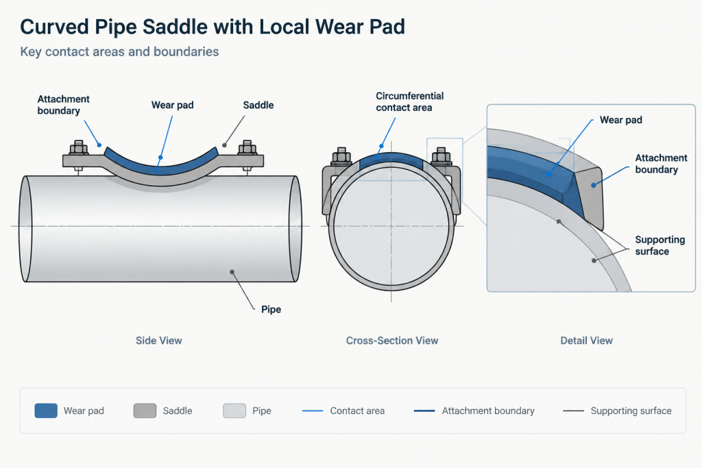
Attachments welded to pressure-containing pipe require engineering and specification review. CAD users should not select pad material, thickness, weld pattern, or attachment extent by visual convention. Those details can affect compatibility, inspection, corrosion behavior, fatigue, and local stresses.
Model the Load Path, Not Just the Shape
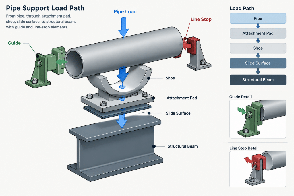
A useful support model makes the load path understandable. Review the assembly from the pipe downward:
- Identify the pipe surface or attachment pad receiving the load.
- Show the saddle, clamp, shoe, or other component transferring that load.
- Show the bearing or sliding interface.
- Show the beam, bracket, sleeper, or other supporting structure.
- Identify guides, stops, hold-downs, or anchors that introduce directional restraint.
If any link is missing, the model may look complete while remaining ambiguous for stress review, structural coordination, fabrication, or installation. Structural members should also be modeled to the correct supporting elevation rather than adjusted visually to meet an incorrectly placed shoe.
Insulation and Coating Interfaces
Insulation frequently determines the configuration of a shoe or saddle. The support may need to maintain clearance around the insulated pipe, pass through the insulation system, or work with a load-bearing insulation insert. Weather barriers and vapor-retarder continuity may also influence the detail.
CAD should distinguish the pipe outside diameter from the insulation envelope. Modeling only the pipe can conceal clashes between insulation and a shoe web, clamp, guide, or adjacent steel. Conversely, placing a support against the insulation envelope does not prove that the insulation system can carry the load.
External coatings also deserve attention at welded attachments and contact areas. The drawing should identify coating boundaries or restoration responsibilities when those requirements are part of the project documentation. Do not assume that a pad automatically eliminates coating damage or corrosion risk.
Movement and Restraint Checks
Supports must be reviewed in both the modeled position and the expected movement range supplied by the responsible engineering discipline. A shoe that fits neatly on a beam in the reference position may approach the beam edge after thermal movement. A guide may bind if its clearances, orientation, or moving envelope are represented incorrectly.
- Check that the bearing surface remains supported through the required travel.
- Confirm that guide elements act in the intended direction.
- Keep line stops distinct from lateral guides.
- Review vertical movement where pipe lift-off or support separation is possible.
- Check adjacent insulation, clamps, welds, and attachments for interference.
- Coordinate the moving shoe with structural bolts, clips, stiffeners, and beam edges.
Movement values and restraint definitions should come from verified project information, not from a generic CAD block.
Drawing and Model Documentation
The required representation depends on the deliverable. A general arrangement may use a support tag and simplified envelope. An isometric may identify the support location and type. A support detail may show the full assembly, while a fabrication drawing may require individual parts, weld information, and material identification.
Use support tags to connect these levels of information. The same identifier should point to the applicable schedule, standard detail, calculated support design, or vendor document. If the model uses a generic placeholder, label it as such and avoid presenting it as fabrication-ready geometry.
Recommended review fields
- Support tag and type.
- Related line number and pipe size.
- Pipe and support elevations.
- Insulated or uninsulated condition.
- Resting, sliding, guided, stopped, held down, or anchored behavior.
- Attachment responsibility and installation stage.
- Applicable detail or support drawing reference.
- Status of engineering, stress, structural, and piping review.
Practical CAD Review Checklist
- Is the component correctly described as a shoe, saddle, pad, or combined assembly?
- Does the curved geometry use the pipe outside surface that it actually contacts?
- Is the complete load path visible or clearly referenced?
- Are insulation and coating interfaces represented or noted?
- Are sliding direction and restraint functions unambiguous?
- Does the shoe remain on its supporting surface through the reviewed movement range?
- Are attachment details based on approved project information rather than library defaults?
- Do the model, isometric, support schedule, and structural drawing use the same support tag and elevation basis?
Pipe shoes, saddles, and wear pads should be modeled as functional interfaces rather than decorative support shapes. Clear separation of bearing, attachment, protection, and restraint functions gives piping, stress, structural, fabrication, and construction teams a common basis for review. Final dimensions, materials, welds, and allowable loads must still be verified against the project’s approved engineering documents.
Applying the Concepts in a CAD Workflow
Begin with the approved support function rather than selecting the closest-looking library object. Establish whether the assembly must provide bearing, surface protection, elevation control, circumferential load distribution, or directional restraint. Several of these functions may be present, but they should remain identifiable as separate parts of the assembly.
Separate geometry from engineering status
A support object can be geometrically accurate while its materials, attachments, welds, and load capacity remain unverified. CAD properties or notes should make that status clear. Generic objects are useful for space allocation and coordination, but they should not appear fabrication-ready unless they have been reconciled with approved project documents.
Use contact surfaces as the modeling basis
Identify the actual surface contacted by each component. Depending on the approved detail, that may be the bare pipe surface, an attachment pad, a saddle, an insulation insert, a slide interface, or another defined layer. This prevents a visually plausible model from concealing an impossible or incomplete bearing arrangement.
Coordinate ownership at interfaces
Support assemblies often cross piping, stress, structural, insulation, coating, fabrication, and construction responsibilities. Documentation should identify who defines the pipe attachment, who supplies the supporting steel, and who verifies movement and restraint. Clear ownership is especially important where a shoe meets a beam or where welded attachments affect the pipe surface.
Keep reusable CAD content controlled
Library components should carry descriptive names and editable properties that reflect function rather than appearance alone. Useful fields include support identity, component role, contact condition, movement behavior, insulation condition, drawing reference, and review status. Project-approved information should replace placeholders before the model is issued for fabrication or construction.
Frequently Asked Questions
Is a pipe shoe automatically a sliding support?
No. A shoe provides a load-transfer interface, but its restraint behavior depends on the complete assembly. Slide surfaces, guides, stops, hold-downs, and anchors must be identified separately.
Should a saddle be modeled to nominal pipe size?
The curved contact geometry should correspond to the actual outside surface it is intended to fit. The model must also account for whether contact occurs at bare pipe, a pad, insulation, or another project-defined layer.
Can a wear pad be shown as the complete support?
Only when the approved design establishes that representation. A wear pad commonly forms one part of a larger load path, so the bearing component and supporting structure should be shown or clearly referenced.
Does a curved pad reinforce the pressure boundary?
Its shape alone does not establish a reinforcement function. Any pressure-boundary role must be supported by approved engineering and specification requirements rather than inferred from CAD geometry.
What should a generic support model communicate?
At minimum, it should make the contact location, support elevation basis, load path, movement behavior, insulation interface, and placeholder status understandable. Final attachment and fabrication details must come from controlled project information.
Why should guides and stops be modeled separately from the shoe?
The shoe carries load to the supporting surface, while guides and stops control movement in defined directions. Separating them reduces ambiguity during stress, piping, and structural review.
How should support changes be coordinated?
Update the model, support tag, schedule, referenced detail, and affected drawings together. A geometry change should also be reviewed for its effect on movement, insulation, structural contact, and attachment requirements.