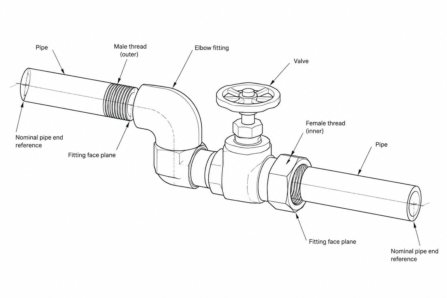
Threaded pipe connections in CAD require more than aligning component centerlines. The model must distinguish the fitting face, connection port, nominal pipe-end position, and component datum so that visually correct geometry does not produce an incorrect fabrication length.
This guide explains how engagement, makeup, takeout, orientation, and assembly sequence affect threaded piping layouts. It is intended to help designers and drafters create models that support coordination and cut-length control without presenting nominal thread geometry as an exact field condition.
Key Drafting Objective
A dependable threaded-piping model should show where components belong, how they connect, and what information controls fabrication. It should not imply that the pipe bottoms inside the fitting or that every assembled joint reaches an identical axial position.
Threaded piping may look simple in a CAD model: place a fitting, extend a pipe to it, and connect the centerlines. The fabrication geometry is less obvious. A threaded pipe end enters the fitting, but its final position depends on the thread form, component dimensions, manufacturing tolerances, sealant, assembly method, and required orientation.
This makes threaded connections different from fixed face-to-face assemblies. A designer should not assume that the visible end of a fitting is the exact termination point of the pipe or that thread engagement is equivalent to a socket-weld insertion depth. Reliable drawings separate nominal layout geometry from the information needed to cut and assemble the pipe.
What a Threaded Connection Represents
A typical threaded piping joint consists of an externally threaded pipe or nipple and an internally threaded fitting, valve, or equipment connection. In United States piping work, tapered pipe threads are common, but they are not universal. Straight threads, mechanical couplings, proprietary connectors, and equipment-specific ports may follow different assembly rules.
With a tapered thread, the mating parts tighten as their thread flanks interfere progressively. The assembled position is therefore not defined by pushing the pipe against an internal shoulder. The pipe advances through an initial engagement region and then reaches its final makeup position as torque is applied.
Three concepts should be kept separate:
- Thread length: the axial extent of the external or internal threaded region.
- Engagement: the portion of the mating threads that overlaps in the assembled joint.
- Makeup: the rotational and axial advance used to tighten the joint from its initial engagement condition.
These terms are related, but they are not interchangeable. The full external thread length does not necessarily disappear inside the fitting, and the final pipe-end position should not be inferred from schematic CAD graphics.
Why the Pipe End Usually Does Not Reach a Fixed Stop
A socket-weld fitting commonly provides a defined socket geometry that can be represented using a specified insertion condition and assembly practice. A tapered threaded fitting behaves differently. Its internal threads control tightening before the pipe end necessarily contacts the bottom of the fitting cavity.
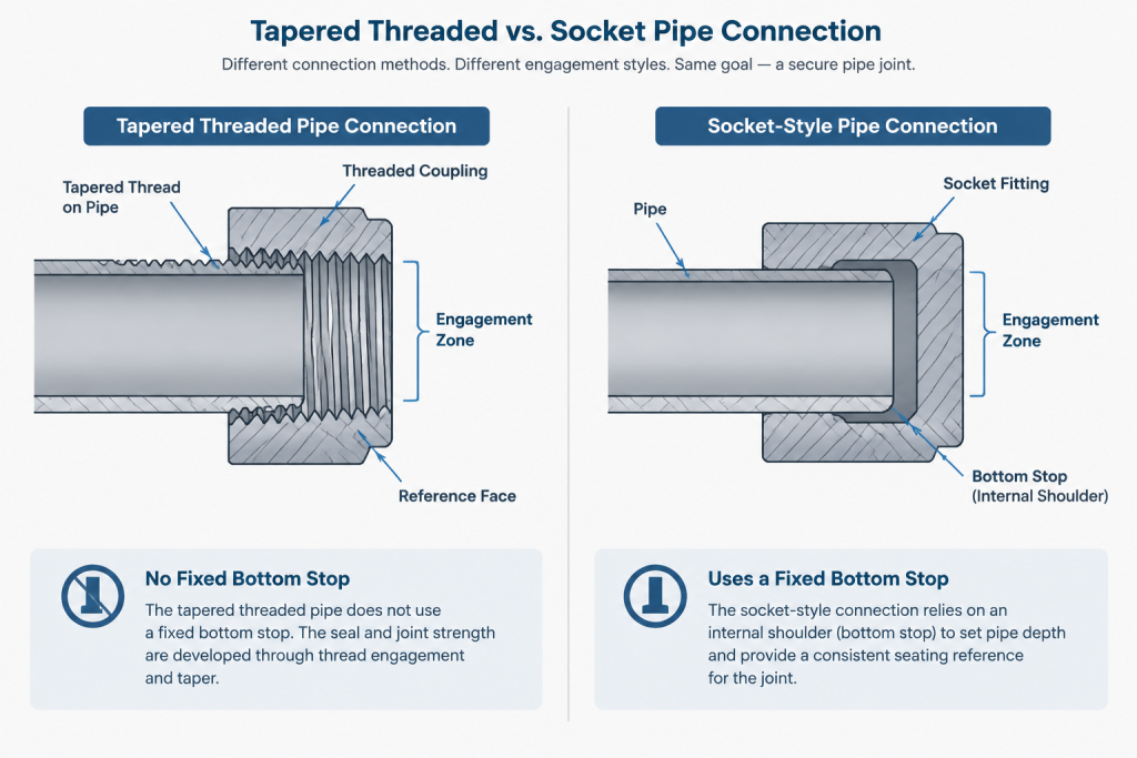
For this reason, extending a modeled pipe to an arbitrary internal wall can create a false cut length. It can also imply that the joint seals at the pipe end when the actual sealing and mechanical engagement occur along the mating threads.
The final position can vary because of:
- Permitted thread and component manufacturing tolerances
- Condition of the male and female threads
- Thread sealant or tape used by the project
- Assembly torque and field workmanship
- Coatings, plating, or surface treatment
- The need to orient an elbow, tee, valve, or instrument connection
CAD geometry should therefore communicate a controlled nominal assembly position without claiming unrealistic precision.
Useful Reference Points for CAD Models
A threaded component library needs consistent insertion points. The most useful connection reference is usually located on the component centerline at a clearly defined port plane. That plane may represent the fitting end face, a catalog connection point, or another documented library convention.
The important requirement is consistency. If one elbow uses its end face as the port while another uses a nominal pipe-end location, automated routing and cut-length calculations can produce inconsistent results.
| Reference | Practical CAD use | Common risk |
|---|---|---|
| Fitting end face | Stable placement and visible component envelope | Does not by itself define final pipe-end position |
| Nominal pipe-end position | Can support cut-length calculations when based on verified data | May be mistaken for an exact field condition |
| Component center or intersection | Convenient for routing elbows and tees | Requires a verified takeout to each connection |
| Manufacturer connection point | Useful for valves and specialty items | Must not be transferred to other products without verification |
Each CAD block or model component should document what its ports mean. A port labeled only as “threaded” is incomplete if users cannot determine whether the insertion point is at the face or at a nominal assembled pipe end.
Fitting Takeout and Pipe Cut Length
For an assembly between two threaded components, the center-to-center layout distance is not normally the same as the pipe cut length. The designer must account for the distance from each component center or datum to the nominal location of the inserted pipe end.
A practical conceptual relationship is:
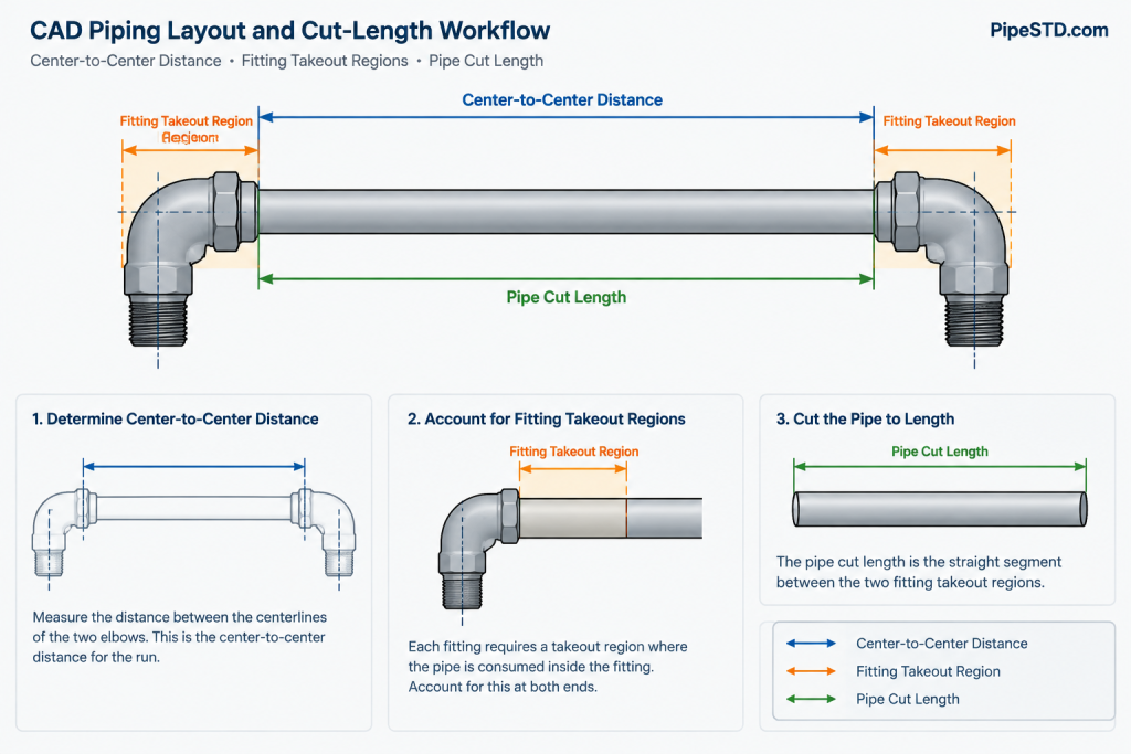
Pipe cut length = layout distance minus the connection takeout at each end
The applicable takeouts must come from verified dimensional references, approved manufacturer information, or a controlled company standard. They should not be measured from a plotted symbol or estimated from the outside shape of a generic CAD block.
Threading also affects fabrication planning. The shop generally starts with a cut pipe length and then forms threads at its ends. The drawing workflow must make clear whether a reported length is the raw cut length before threading, the finished nipple length measured end to end, or the nominal distance between assembled components. Mixing these definitions can create a spool that is too long or too short.
Close-Coupled Assemblies Need Extra Care
Short nipples between fittings, valves, strainers, unions, and instruments leave little room to absorb dimensional assumptions. In these assemblies, the external threads from opposite ends may occupy much of the nipple length. A generic visual model can conceal whether the selected nipple configuration is physically available or whether tools can make up the connections.
Do not generate a short threaded piece solely by subtracting two CAD takeouts. Verify the required nipple type, end-to-end convention, thread arrangement, procurement method, and assembly sequence.
Orientation Changes the Assembly Problem
A coupling can usually be tightened without needing a particular final rotational position. An elbow, tee, valve, gauge, or branch connection often must finish at a specific orientation. The installer may reach the required direction before or after the preferred nominal makeup condition.
The drawing should avoid implying that a tightly controlled angular orientation and an exact axial position are both guaranteed by an ordinary tapered-thread joint. Where orientation is critical, the design may need an adjustable connection, union, flange, swivel arrangement, or another project-approved solution.
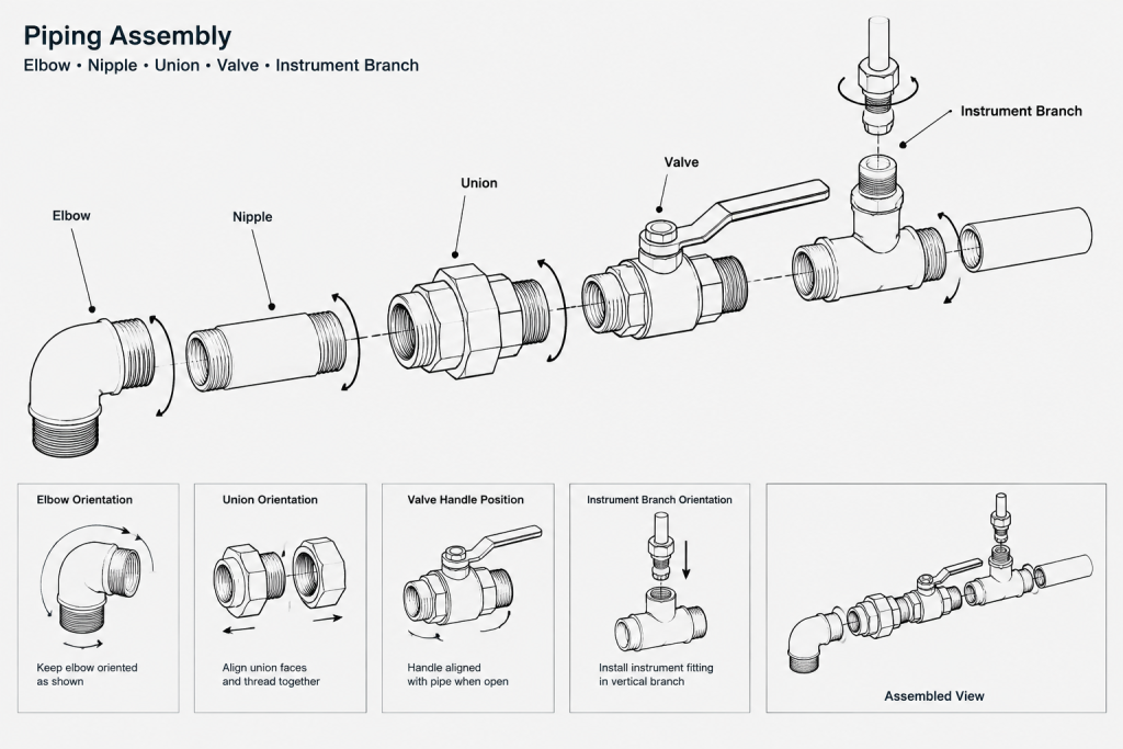
For CAD coordination, show the required functional orientation of the component. For fabrication, add only the notes and dimensions authorized by the project specification. Do not solve an orientation conflict by visually rotating a model while leaving an impossible connection sequence.
Single-Line, Double-Line, and 3D Representation
Single-Line Drawings
On schematics and many small-bore isometrics, the centerline and connection symbol carry most of the information. Threads are typically identified by the component description, end-connection code, piping specification, or note rather than by drawing individual thread forms.
Double-Line Details
A detail may show the pipe entering the fitting and may use simplified thread graphics to explain assembly. The drawing should distinguish diagrammatic thread lines from machinable thread geometry. Enlarged graphics are useful for communication but should not be scaled to derive engagement.
Three-Dimensional Models
Full helical threads create unnecessary model complexity for most plant-layout work. A simplified cylindrical or tapered connection zone is usually more practical. Detailed thread geometry may be appropriate for specialized fabrication or interference analysis, but it must be generated from verified requirements rather than decorative modeling.
Threaded Connection CAD Checklist
- Confirm the actual thread system instead of assuming every threaded port is the same.
- Verify component end connections against the piping material specification and vendor data.
- Use a consistent port-plane convention across the component library.
- Separate fitting face, nominal pipe-end position, and fitting center in the model data.
- Use verified takeout information for cut-length calculations.
- Identify whether a listed nipple length is end-to-end, finished, or an assembly dimension.
- Check component orientation and the number of joints that must be rotated during installation.
- Provide unions or other approved break points where the assembly sequence requires them.
- Review wrench access around valves, instruments, and closely spaced fittings.
- Do not dimension from symbolic thread graphics or an unverified generic block.
- Flag equipment and specialty-component ports that require manufacturer-specific data.
- Treat the modeled engagement as nominal unless the project documents define another basis.
A Better Modeling Principle
The most dependable approach is to model threaded piping around controlled connection references, not around an assumed physical bottoming point. The CAD component should provide a stable port, a verified dimensional basis, and enough metadata to identify the end connection. The drawing should then communicate layout, orientation, access, and fabrication intent without presenting nominal engagement as an exact field result.
This distinction improves cut-length control and makes threaded assemblies easier to review. It also helps prevent a common drafting error: producing visually connected geometry that cannot be assembled, oriented, or fabricated as shown.
Applying the Concept in a Controlled CAD Workflow
The connection convention should be established at the library or project level rather than decided separately by each modeler. Component records can identify the port plane, component datum, connection type, and approved source of takeout information. Keeping these definitions with the component reduces the risk of users measuring an outside profile or symbolic thread graphic.
Separate Layout Data From Fabrication Data
Layout geometry answers where the fitting, valve, or instrument belongs in the system. Fabrication data answers how the pipe is cut, threaded, and assembled. These purposes are related, but a single visible endpoint may not communicate both reliably.
- Layout model: controls centerlines, component locations, orientation, clearance, and access.
- Connection metadata: identifies the port convention and verified takeout basis.
- Fabrication output: states the applicable length definition and avoids ambiguous endpoint assumptions.
- Review process: checks assembly order, wrench access, removable sections, and orientation-sensitive joints.
Quality Checks for Automated Cut Lists
Automated reports are only as dependable as the component definitions behind them. Before accepting a calculated cut length, confirm that both connected ports use the same modeling convention and that the report applies the intended takeout data. Specialty components and manufacturer-defined ports should be reviewed separately rather than treated as interchangeable with generic fittings.
Revisions also require care. Replacing a component with another item that has a different connection reference can alter the required pipe length even when the routed centerline appears unchanged. A replacement-safe workflow compares port locations, takeouts, end-connection definitions, and installation orientation before updating fabrication information.
Drawing and Model Review Questions
- Does the component port represent a face, a nominal assembled pipe end, or another documented datum?
- Is the cut-length calculation based on controlled data rather than scaled graphics?
- Can the assembly be rotated and tightened in the modeled installation sequence?
- Is the required final orientation compatible with the selected connection arrangement?
- Are access, removal, and maintenance needs visible in the layout?
- Does the deliverable clearly distinguish pipe length from center-to-center or face-to-face layout dimensions?
These checks help turn a connected CAD model into a useful engineering record while preserving the distinction between nominal design geometry and actual assembly variation.
Frequently Asked Questions
Should a CAD pipe end be extended to the bottom of a threaded fitting?
No general bottoming assumption should be used. The modeled endpoint should follow the documented component-library convention and verified connection data.
Are thread length, engagement, and makeup the same thing?
No. Thread length describes the threaded region, engagement describes the overlap between mating threads, and makeup describes the tightening advance during assembly.
Can a fitting face be used directly to calculate pipe cut length?
Not by itself. A face can be a stable placement reference, but cut-length calculations also require verified takeout information and a clear definition of the reported pipe length.
Why can an oriented threaded component be difficult to model accurately?
An elbow, tee, valve, or instrument must tighten while also reaching its required direction. The desired rotational orientation may not coincide with a single exact axial position.
Should detailed helical threads be modeled in plant-layout CAD?
Usually, simplified connection geometry communicates the layout more efficiently. Detailed thread geometry should be reserved for workflows that require it and should be based on verified requirements.
What should be checked when replacing a threaded CAD component?
Review the port datum, takeout basis, end-connection definition, component envelope, orientation, access, and assembly sequence. A visually similar replacement may not preserve the same pipe cut length.
Can pipe lengths be measured from a generic CAD block?
Only when the block has controlled, documented, and verified dimensional data. Symbolic or unverified graphics should not be treated as fabrication references.