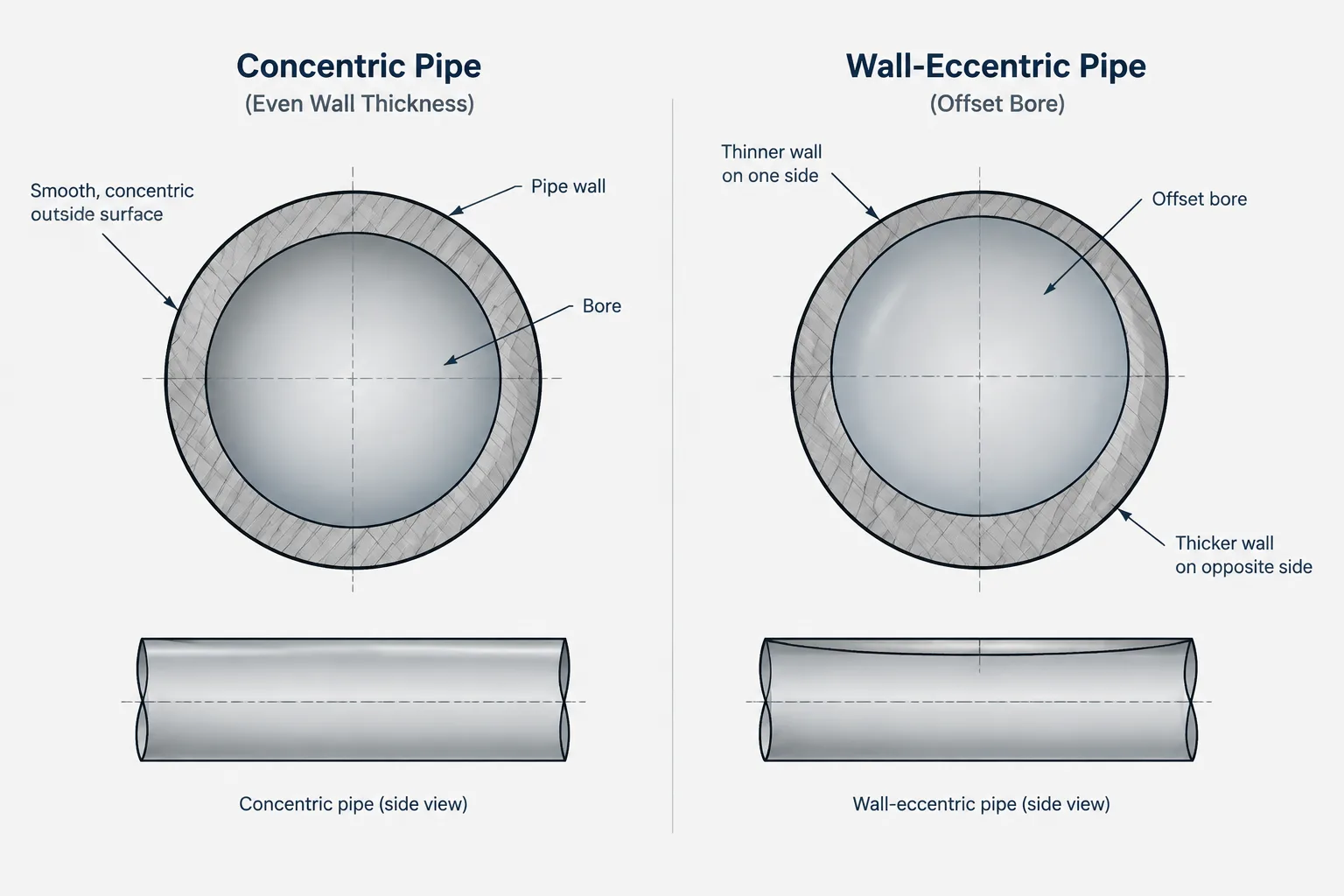
Pipe wall eccentricity explains why the center of a pipe bore may not coincide with the center implied by its outside diameter. The distinction matters when nominal CAD geometry is compared with inspection readings, prepared pipe ends, or actual internal alignment at a joint.
This guide separates ideal concentric geometry from measured pipe conditions and shows when designers can rely on nominal data—and when fabrication or integrity decisions require documented field or shop measurements.
A piping model usually represents pipe as two concentric cylinders: one for the outside diameter and one for the bore. Real pipe is not geometrically perfect. Its inside and outside surfaces may not share exactly the same center, producing unequal wall thickness around the circumference. This condition is commonly described as pipe wall eccentricity.
Eccentricity is easy to overlook because nominal pipe size, schedule, outside diameter, and listed wall thickness describe a standardized product category rather than a perfect manufactured cross-section. Understanding the difference helps designers interpret inspection results, evaluate butt-weld fit-up, and avoid placing unrealistic confidence in ideal CAD geometry.
What Is Pipe Wall Eccentricity?
A pipe wall is concentric when the bore and outside surface are centered on the same axis. If the bore is offset relative to the outside surface, one side of the wall is thicker and the opposite side is thinner. The pipe can still have an acceptable outside diameter while exhibiting measurable variation in local wall thickness.
This is not the same as saying that the entire pipe is installed off-center. Wall eccentricity is a characteristic of the pipe cross-section itself. A pipe centerline in a model or layout generally follows the nominal axis of the component; it does not attempt to track small manufacturing variations in the actual bore.
The familiar relationship between outside diameter, inside diameter, and wall thickness assumes an ideal circular, concentric section:
Ideal inside diameter = outside diameter − twice the wall thickness
That relationship is useful for reference calculations, but a real pipe may not have one uniform measured inside diameter or one identical wall reading around its circumference.
Eccentricity Is Not the Same as Ovality
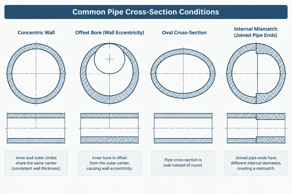
Wall eccentricity and ovality can occur together, but they describe different geometric conditions.
| Condition | What varies | Typical geometric interpretation |
|---|---|---|
| Wall eccentricity | Local wall thickness around the circumference | The inside and outside surfaces do not share the same center |
| Ovality or out-of-roundness | Diameter measured in different directions | The cross-section is not perfectly circular |
| Bore mismatch | Internal alignment across a joint | Two connected components have different or offset internal surfaces |
| Pipe straightness variation | Axis position along the pipe length | The pipe has bow, sweep, or local deviation from a straight line |
A pipe can be nearly round on its outside surface while its bore is slightly offset. Conversely, an out-of-round pipe can have a reasonably uniform wall if its inside and outside shapes follow one another. Measurements must therefore be interpreted according to what was actually inspected.
Why Schedule Does Not Define Every Local Wall Reading
Pipe schedule identifies a nominal wall-thickness series for a given nominal pipe size. It does not mean that every point on every manufactured pipe has exactly the listed nominal wall. Manufacturing processes, dimensional tolerances, surface condition, and subsequent forming can produce local variation.
The selected schedule also should not be treated as an inspection acceptance rule by itself. Acceptance depends on the applicable material or product specification, the project piping specification, purchase requirements, and any additional engineering criteria. Those documents determine which tolerances and verification methods apply.
For CAD and preliminary calculations, nominal dimensions are normally appropriate. For minimum-wall evaluation, remaining-life assessment, machining, or weld preparation, measured or guaranteed values may be required instead.
How CAD Models Represent the Pipe Bore
Most piping CAD models use idealized geometry. The pipe outside surface and bore are typically circular and concentric, with the wall based on database dimensions. This is intentional: modeling every permitted manufacturing variation would add complexity without improving ordinary plant-layout work.
An ideal model is generally suitable for:
- Routing and centerline control
- Interference and clearance reviews
- Nominal material takeoffs
- Insulation envelope modeling
- General arrangement and isometric production
- Typical fitting and flange connection geometry
It is not, by itself, proof of:
- Uniform wall thickness in delivered material
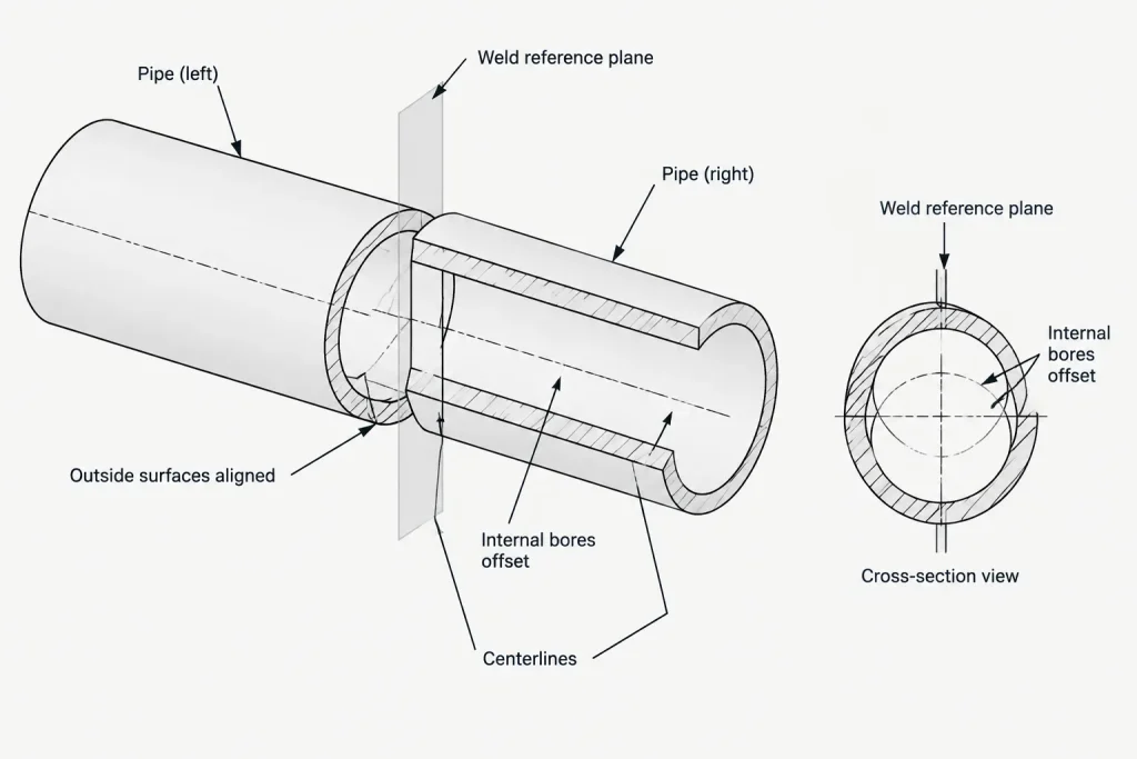
- Exact internal alignment at a field or shop weld
- Compliance with minimum-wall requirements
- Machining stock available at a specific pipe end
- The measured bore of an existing pipe
If an application depends on actual bore position, the model should be supplemented by inspection data, fabrication instructions, or a project-specific detail rather than modified to imply an unverified measured condition.
Where Wall Eccentricity Matters in Practice
Butt-Weld Fit-Up
When two pipe ends are aligned by their outside surfaces, unequal wall distribution can create internal offset even if their nominal sizes and schedules match. Rotating one pipe may improve local bore alignment, but that decision belongs to fabrication control and must remain consistent with material identification, seam-orientation rules, branch locations, and other project requirements.
A generic CAD model cannot predict the best rotational position because the actual wall map is usually unknown during design.
End Preparation and Machining
Counterboring, tapering, or other end preparation may be used in some applications to manage internal transitions. Available wall must be verified before removing material. A nominal model should not be used to conclude that sufficient machining allowance exists at every point around the circumference.
Inspection and Remaining Wall Evaluation
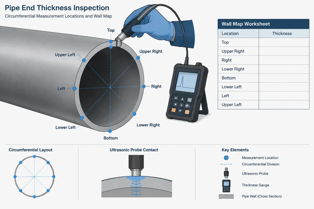
A single thickness reading establishes the wall only at the measured location. When eccentricity, localized thinning, or degradation is a concern, inspection may require readings at multiple circumferential and longitudinal positions. The required coverage and acceptance criteria should come from the applicable inspection plan and engineering procedure.
Existing-System Tie-Ins
Older pipe may combine original manufacturing variation with corrosion, erosion, deposits, lining, deformation, or previous repairs. Nominal schedule data is useful for identifying the expected product, but it is not a substitute for field measurement when a tie-in depends on actual wall or bore geometry.
Flow and Cleaning Applications
Small manufacturing variations are not normally modeled in routine hydraulic layouts. However, pronounced internal steps or offsets at joints may matter in services sensitive to deposits, cleaning, pigging, erosion, or localized turbulence. In those cases, the relevant issue is usually the assembled internal transition, not merely the presence of wall eccentricity in an individual pipe length.
Useful Ways to Document the Condition
The design model should remain based on controlled nominal data unless verified as-built geometry is intentionally being recorded. When additional control is necessary, supporting documents can carry the information more clearly.
- Inspection report: Record thickness readings with identifiable circumferential and longitudinal locations.
- Pipe-end map: Show the distribution of measured wall around an end prepared for welding or machining.
- Fabrication note: State required fit-up checks without implying that nominal CAD geometry represents the delivered material.
- Weld detail: Define any project-approved transition or preparation needed to address internal mismatch.
- As-built record: Distinguish measured field geometry from catalog or database dimensions.
- Hold point or inspection point: Identify where verification is required before irreversible fabrication proceeds.
Notes should specify what must be measured or checked rather than relying on vague instructions such as “align bore.” The required reference surface, inspection stage, and controlling document should be clear.
A Practical Review Workflow
- Identify why actual wall distribution matters. Ordinary routing usually needs nominal geometry; machining, critical fit-up, or condition assessment may require measurements.
- Confirm the governing documents. Review the product specification, piping material specification, purchase requirements, welding documents, and inspection plan as applicable.
- Separate nominal data from measured data. Do not overwrite a catalog dimension with one field reading without recording its source and scope.
- Inspect enough locations for the decision. A limited reading pattern may not characterize the full circumference or pipe length.
- Coordinate fabrication actions. Rotation, end preparation, matching, or rejection should be handled through an approved fabrication and quality process.
- Preserve traceability. Keep measurement records associated with the correct pipe piece, end, weld, or spool.
The Key CAD and Engineering Distinction
Pipe wall eccentricity is a real manufacturing and inspection concern, but it is not normally represented in a standard piping model. The CAD component shows the nominal design envelope and an idealized bore. Delivered material may have circumferential wall variation within the limits applicable to that product and project.
Designers should therefore use nominal dimensions for their intended purpose while recognizing when fabrication or integrity decisions require actual measurements. Keeping ideal geometry, specified limits, and measured conditions separate prevents both over-modeling and false precision.
Three Centerlines That Should Not Be Confused
Discussions about an “off-center” pipe can refer to different geometric references. Keeping those references separate helps prevent incorrect conclusions from inspection data or CAD views.
- Model centerline: The nominal routing axis used to locate pipe, fittings, supports, and connected equipment in the design model.
- Outside-surface center: A center inferred from measurements of the actual outside surface at a particular cross-section.
- Bore center: A center inferred from the internal surface at that same cross-section.
In ideal CAD geometry, these references coincide. In delivered pipe, the bore center and outside-surface center may differ. The result does not necessarily mean that the modeled route, pipe support location, or installed spool centerline is incorrect.
Condition Description Is Not an Acceptance Decision
Calling a cross-section eccentric describes its geometry; it does not by itself establish whether the pipe is acceptable or defective. Acceptance must be evaluated against the documents governing the supplied material, fabrication activity, inspection scope, and intended service.
The same separation is important when reviewing a wall-thickness report. A local reading may identify a thinner or thicker area, but the engineering significance depends on where the reading was taken, how the location was referenced, whether the result is repeatable, and which acceptance basis applies.
Questions to Resolve Before Acting on a Measurement
- Does the result represent nominal database geometry, a supplier record, or an actual measurement?
- Is the reported location tied to an identifiable pipe piece, end, weld, or spool?
- Was the position recorded around the circumference and along the pipe length?
- Is the concern local wall thickness, bore alignment, outside-surface shape, or pipe straightness?
- Does the proposed action affect end preparation, material traceability, seam orientation, or another controlled fabrication requirement?
- Which engineering, fabrication, or quality document authorizes the final disposition?
This decision trail is more reliable than attempting to make the nominal CAD bore resemble an isolated measurement. The model can continue to communicate design intent while inspection and fabrication records document the physical condition.
Frequently Asked Questions
Can pipe have the correct outside diameter and still have wall eccentricity?
Yes. The outside surface may remain within the applicable requirements while the bore is offset, producing different local wall readings around the circumference. Outside-diameter information alone does not establish uniform wall thickness.
Is pipe wall eccentricity the same as an eccentric reducer?
No. Pipe wall eccentricity is variation within a pipe cross-section caused by the bore and outside surface not sharing the same center. An eccentric reducer is an intentionally shaped fitting used to connect different pipe sizes while maintaining a selected alignment relationship.
Does a schedule define the actual bore centerline?
No. Schedule identifies a nominal wall-thickness series. It supports standardized design and database geometry but does not identify the measured position or shape of the bore in an individual pipe length.
Can a CAD model be used to check internal weld mismatch?
A nominal model can illustrate the intended connection, but it cannot prove the internal alignment of delivered components. A reliable fit-up decision may require actual pipe-end measurements and the fabrication checks specified by the project.
Does rotating a pipe always correct bore mismatch?
Not necessarily. Rotation may improve alignment in some cases, but the result depends on the measured wall distribution of both ends. Rotation also must not conflict with controlled seam orientation, branch placement, traceability, or other fabrication requirements.
Should measured eccentricity be added to the piping model?
Usually not for routine design modeling. If actual geometry is important to a tie-in, machining operation, or integrity assessment, it is generally clearer to preserve the measurement in a traceable inspection record, pipe-end map, fabrication detail, or verified as-built deliverable.