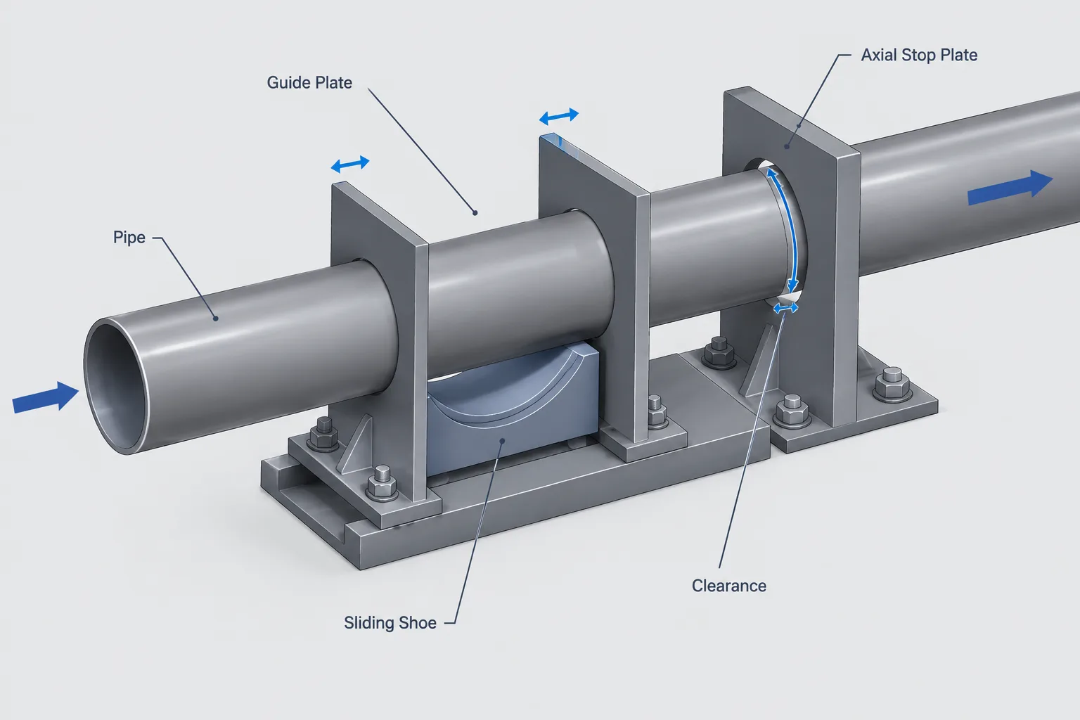
Piping guide gaps and line stops in CAD must communicate more than support geometry. They must show which movement is permitted, which direction is restrained, where contact occurs, and whether a clearance must close before the restraint becomes active.
This reference explains how to interpret and document those functions across the model, support schedule, stress-analysis data, fabrication details, and installation instructions. The central drafting principle is simple: represent the intended restraint behavior explicitly rather than expecting reviewers or installers to infer it from the shape of the support steel.
Pipe supports do more than carry weight. Some supports permit the pipe to slide while limiting sideways motion; others restrict axial travel in one direction, both directions, or only after a specified clearance closes. These functions are commonly described with terms such as guide, line stop, directional restraint, and gap.
In CAD, the support steel may look simple, but its functional behavior is not always obvious from geometry alone. A small clearance between a pipe shoe and a stop plate can determine whether the support is initially free, engages during thermal movement, or acts in only one direction. Designers therefore need to coordinate the physical model, support schedule, stress-analysis data, drawings, and installation requirements rather than relying on a generic support symbol.
What a pipe guide is intended to do
A pipe guide generally limits lateral movement while allowing movement along the intended pipe axis. For a straight run, this often means that the pipe or its shoe can slide axially but cannot move freely from side to side.
The word guide describes a restraint function, not one universal piece of hardware. A guide may use structural members beside a pipe shoe, a clamp assembly, a fabricated frame, or another project-specific arrangement. Its geometry must suit the pipe, insulation system, support attachment, expected movement, and surrounding structure.
A guide is also not automatically an anchor. An anchor is intended to restrain movement in multiple directions and may control rotation as defined by the design. A guide normally leaves at least one translation direction substantially free. Treating the two as interchangeable can change the piping system’s load path.
How a line stop differs from a guide
A line stop restricts movement along the pipe axis. Depending on its configuration, it may resist axial movement in both directions or only after the pipe moves toward a stop surface. Line stops are often used to distribute thermal growth, limit movement near equipment, or establish the intended behavior of a flexible piping system.
A support can combine functions. For example, one assembly may carry vertical load, guide the pipe laterally, and stop axial motion in a selected direction. The model should not reduce that combined behavior to a single ambiguous label if the distinction affects fabrication, analysis, or installation.
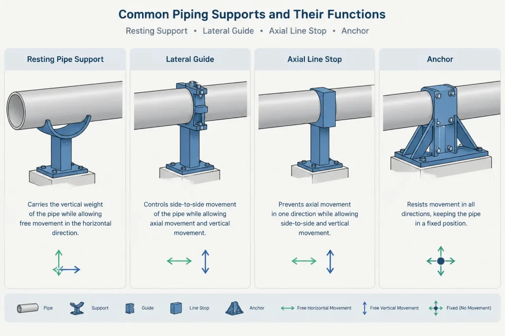
| Support function | Movement generally restricted | Movement that may remain available | CAD documentation concern |
|---|---|---|---|
| Resting support | Downward vertical movement at the contact surface | Sliding or lift-off may be possible | Show bearing elevation and contact arrangement |
| Guide | Lateral movement relative to the pipe axis | Axial sliding | Identify guide direction and side clearances |
| Line stop | Axial movement in one or both directions | Lateral sliding may depend on the assembly | Identify active stop faces and axial gaps |
| Anchor | Multiple translations and possibly rotations | Only behavior intentionally released by the design | Do not represent it as a generic guide or stop |
These descriptions are conceptual. The actual restraint directions and allowable movements must come from the project design and stress-analysis requirements.
What a support gap means
A gap is an intentional clearance between surfaces that may come into contact as the pipe moves. Before the gap closes, the restraint does not act in that direction through direct contact. After closure, the stop or guide can begin resisting additional movement, subject to deformation, friction, and the actual support design.
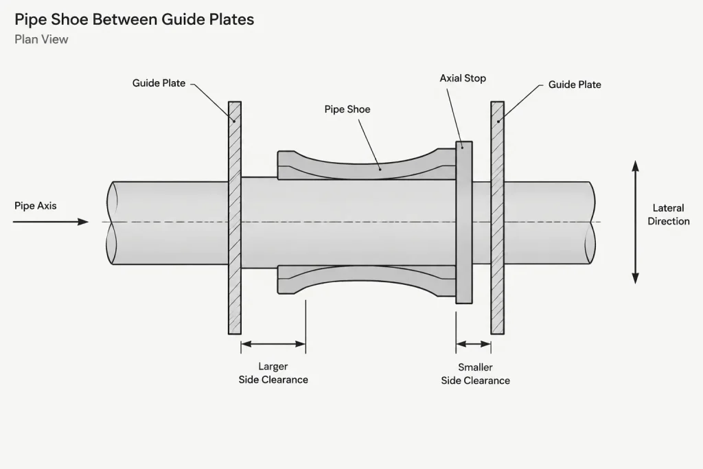
Gaps may be provided on one side or both sides. Unequal gaps can produce directional behavior, while equal clearances may allow limited movement around the installed position. A zero-clearance restraint and a gapped restraint should not be treated as equivalent in either the stress model or the support drawing.
Designers should clarify what condition a stated gap represents. It may refer to the required installation clearance, the nominal modeled position, or a condition associated with a defined temperature or operating state. A gap value without a reference condition can be misinterpreted in the shop or field.
Gap is not the same as tolerance
An intentional movement gap is a design feature. Fabrication and installation tolerances describe permitted variation in the completed work. If a required clearance is important to system behavior, its nominal requirement and applicable tolerance need coordinated documentation. The visible space in a perfectly exact CAD model does not by itself establish what field variation is acceptable.
Establish the restraint coordinate system
Terms such as axial, lateral, north, east, and vertical are meaningful only when their reference system is clear. For a straight horizontal pipe, the axial direction follows the pipe centerline. For a skewed or sloped run, the pipe axis may not align with a plant coordinate axis.
The CAD model, stress model, and support schedule may also use different axis conventions. A restraint described as local X in one system could appear as a combination of plant-coordinate directions in another. Before transferring support data, confirm:
- whether restraint directions are local to the pipe or global to the plant;
- the positive and negative direction convention;
- whether the support acts on the pipe, shoe, clamp, or structural frame;
- the location used as the support node or reference point;
- whether rotation is restrained, released, or simply not documented;
- the installation condition associated with any specified gap.
Directional arrows and plain-language notes can prevent errors that are difficult to detect from restraint codes alone.
Modeling guides and stops in 3D CAD
The required level of geometric detail depends on the model’s purpose. Early layout models may use a simplified support envelope and an assigned support type. Detailed coordination models may need the pipe shoe, guide plates, stop members, attachment plates, weld access, structural connections, and movement space.
Whatever level is selected, model the functional contact surfaces deliberately. The important dimension is often not the overall width of the support but the clearance between the moving and stationary parts. Check that the model represents the intended initial position rather than an arbitrary visually centered arrangement.
Useful model data fields may include the support identifier, support type, pipe line number, restraint directions, gap direction, gap requirement, design responsibility, drawing reference, and status. Avoid embedding unverified stress results into reusable CAD components. A library object can provide geometry and metadata fields, but project-specific behavior must be assigned and reviewed for each application.
Account for the movement envelope
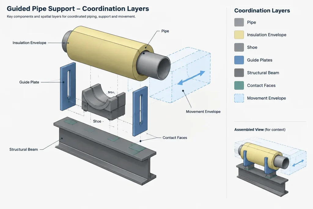
A pipe shoe that slides through a guide needs adequate bearing length and unobstructed travel. Adjacent steel, insulation, drains, clamps, bolts, and secondary supports must not enter the expected movement path. The support should also remain engaged as intended throughout the evaluated displacement range.
Displaying both the installed geometry and a separate movement envelope can make coordination clearer. The envelope is a review aid, not a claim that the piping will occupy every intermediate position or that the indicated movement has been independently verified.
What to show on support drawings
A support drawing should communicate how the assembly is built and how it is positioned. Where guide or stop behavior is critical, consider showing:
- the pipe centerline and support reference elevation;
- the support identifier and associated line identification;
- the axial and lateral directions;
- the active guide or stop faces;
- clearances on each applicable side;
- the condition at which the clearances are to be set;
- shoe, clamp, insulation, and structural interfaces;
- adjustment or field-setting requirements, when specified;
- references to the controlling support standard or project detail.
Do not assume that a symmetric detail implies equal gaps. If only one side is intended to engage, indicate that direction explicitly. Likewise, avoid dimensioning the same gap independently in several views unless the drawing-control method prevents conflicting values.
Coordination between piping, stress, structural, and construction teams
Guide and stop design crosses discipline boundaries. Piping layout establishes the route and physical location. Stress analysis defines the required restraint behavior and evaluates loads and displacements. Structural engineering checks the supporting steel and load transfer. Support design converts those requirements into a buildable assembly, while construction sets the support in the required field condition.
Changes must flow back through this chain. Moving a support, reversing a one-way stop, changing a gap, or attaching the assembly to different steel can affect system behavior. A visually minor CAD revision may therefore require stress and structural review.
Common CAD and documentation errors
- Using a generic support symbol without restraint data: Geometry alone may not reveal which directions are controlled.
- Confusing a guide with an anchor: This can misstate both movement freedom and support loading.
- Centering the shoe automatically: The required installed position may use unequal or directional clearances.
- Omitting the gap reference condition: Fabricators and installers may not know when the clearance applies.
- Ignoring insulation and attachments: The bare pipe may clear while the complete moving assembly clashes.
- Mixing local and global axes: Correct restraint data can be applied in the wrong physical direction.
- Updating CAD without updating analysis: Support location and behavior are analytical inputs, not drafting details only.
A practical review workflow
Begin with the latest approved restraint requirements and confirm the coordinate convention. Locate each support using controlled piping and structural references. Model the pipe attachment and stationary members at an appropriate level of detail, then represent intentional clearances at the relevant contact faces.
Next, compare the support against reported movement and load directions, check its travel envelope, and review nearby equipment and steel. Coordinate any discrepancy with the responsible engineering disciplines. Finally, verify that the support schedule, model properties, detail drawing, isometric references, and installation notes describe the same behavior.
A guide gap or line stop is small in physical size but significant in system behavior. Clear direction notation, controlled reference conditions, and disciplined coordination turn a simple-looking support into a reliable part of the piping design.
Use a functional handoff check
A support is ready for interdisciplinary handoff only when its geometry, metadata, and drawing notes communicate the same behavior. Review the assembly from the perspective of each downstream user rather than checking only whether the CAD components fit together.
- For piping layout: Confirm that the support location, pipe axis, attachment, and movement space match the routed line.
- For stress analysis: Confirm that the restrained directions, released directions, contact faces, and gaps correspond to the analytical intent.
- For structural review: Identify where restraint forces enter the supporting steel and which members provide the reaction.
- For fabrication: Show which surfaces establish the guide or stop and avoid relying on a visually centered model to define clearance.
- For installation: State the reference condition for setting the support and make directional requirements visible in the field documentation.
Separate geometry from restraint behavior
A reusable CAD component can depict a shoe, plate, clamp, or frame, but the component shape does not prove how the installed assembly will behave. The project application still needs assigned restraint directions, gap information, reference conditions, and engineering review.
This distinction is especially important when similar-looking assemblies perform different functions. A plate beside a shoe may act as a guide face, an axial stop, or part of a combined restraint depending on its orientation and intended contact. Naming the function and marking the active face reduces the risk of a correct-looking model carrying incorrect analytical assumptions.
Questions to resolve before issue
- Is direction defined relative to the pipe axis or the plant coordinate system?
- Does the restraint act immediately, or only after an intentional gap closes?
- Is contact intended on one side or on opposing sides?
- Does the moving envelope include the shoe, clamp, insulation, and attached items?
- Do the model, schedule, detail, and installation note use the same support identifier and behavior description?
- Have changes to location, orientation, or clearance been returned to the responsible engineering disciplines?
If any answer is unclear, the support should be treated as a coordination item rather than resolved through drafting assumptions.
Frequently asked questions
Is a pipe guide the same as a line stop?
No. A guide generally limits movement across the pipe axis while allowing axial sliding. A line stop limits axial movement. A single support assembly may perform both functions, but each restraint direction should be documented separately.
What does a gap mean in a piping restraint?
A gap is an intentional clearance at a potential contact surface. Direct contact restraint in that direction begins only after movement closes the clearance. The documentation should identify the applicable face, direction, and reference condition.
Should a CAD model show the pipe shoe centered between guide plates?
Only when that position reflects the approved design condition. Automatic visual centering can conceal unequal clearances or a one-way restraint. The installed position should follow the coordinated support requirements.
Why is the coordinate system important?
Restraint directions may be expressed relative to the pipe or to the plant. On skewed or sloped piping, those systems may not align. Direction arrows and clear notes help prevent restraint data from being applied along the wrong physical axis.
Is an intentional support gap a fabrication tolerance?
No. The gap defines intended movement behavior, while tolerance defines acceptable variation in fabrication or installation. Both may require documentation, but they serve different purposes and should not be used interchangeably.
Can support geometry be changed without stress review?
Not when the change can affect restraint location, direction, clearance, contact, or load transfer. A small geometric revision may alter piping behavior and should be coordinated with the responsible stress and structural disciplines.
What information belongs in a reusable CAD support object?
The object can contain generic geometry and fields for identification, restraint direction, gap direction, drawing reference, and status. Project-specific loads, movements, and restraint behavior should be assigned from verified project information rather than embedded as universal defaults.