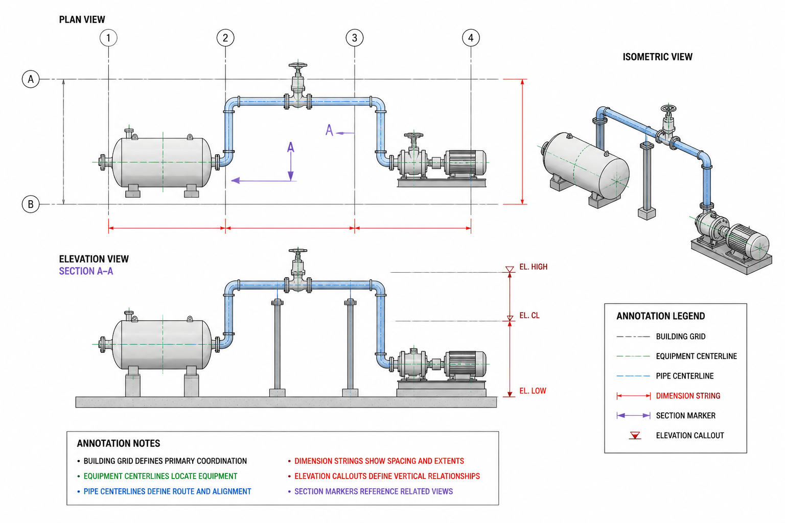
Piping coordinate dimensions in CAD connect a digital route to the physical references used by designers, fabricators, installers, and reviewers. Clear dimensions do more than label a drawing: they identify how the pipe relates to equipment, structure, plant grids, and elevation controls.
This guide explains how to choose reliable datums, dimension piping centerlines, coordinate plan and elevation information, and organize CAD annotations for review. Use it alongside the site’s pipe dimensions and schedules reference, which addresses pipe size and wall-related terminology rather than route location.
Piping coordinate dimensions in CAD turn a drawn route into information that fabricators, installers, and reviewers can verify. A line may look correctly positioned in a plan or isometric view, yet still be difficult to locate in the plant if its reference points, elevations, and connection dimensions are unclear.

The goal is not to dimension every visible graphic element. The goal is to communicate a stable location for the piping centerline, connection points, changes in direction, and important interfaces with equipment or structures. This requires a consistent datum strategy and a deliberate approach to dimension placement.
What piping coordinate dimensions communicate
Coordinate dimensions define where a piping feature is located relative to an agreed reference system. Depending on the project, that reference system may use plant grid lines, building columns, equipment centerlines, structural faces, or established survey datums.
Typical coordinate information may identify:
- The horizontal location of a pipe centerline in plan view.
- The elevation of a pipe centerline, bottom, top, or connection point.
- The position of a valve, branch, flange, instrument connection, or drain.
- The location of a change in direction or a support interface.
- The relationship between piping and equipment nozzles, platforms, walls, or structural members.
- The direction and amount of a required slope, when the design calls for one.
These dimensions supplement, rather than replace, the project’s pipe dimension and schedule data. A schedule identifies properties such as nominal size and wall category; coordinate dimensions identify where the physical route is located.
Start with a reliable datum strategy
Dimensioning becomes confusing when each view uses a different origin. Before adding dimensions, identify the primary datums that the drawing set will use. A datum should be physically identifiable and stable throughout design development.
Common choices include:
- Building grid intersections or grid lines.
- Equipment centerlines and nozzle reference faces.
- Finished floor, structural steel, or a defined elevation datum.
- Plant north, project north, or another documented orientation.
- Survey or civil control points where applicable.
Use the same datum convention across related plans, elevations, and isometrics whenever practical. If a view uses a local origin for clarity, label that origin and explain how it relates to the main project coordinate system. An unexplained local coordinate system can create errors even when every individual dimension is mathematically correct.
Choose the right dimensioning method
There is no single dimensioning method that works for every piping drawing. The best choice depends on how the route will be set out and checked in the field.
Baseline or ordinate dimensions
Baseline dimensions measure several features from one common datum. This approach reduces the risk that small rounding differences accumulate along a route. It is useful when a group of pipe centers, equipment connections, or structural interfaces must remain coordinated with a fixed grid or face.
Keep the baseline clear and make sure each ordinate has an unambiguous witness line. Avoid allowing extension lines to cross unrelated geometry or terminate at a visually similar feature.
Chain dimensions
Chain dimensions show successive distances from one feature to the next. They can be easy to follow for a short, simple run, particularly when the installer works progressively along the route.
However, chain dimensions can hide accumulated differences if each segment is rounded or independently interpreted. For a long route or a route tied to equipment and structure, combine chain information with selected overall or datum-based dimensions.
Coordinate callouts
Coordinate callouts identify a point using values from the project axes and elevation datum. They are useful in congested layouts, three-dimensional models, and drawings where direct dimension strings would obscure the route.
Coordinate callouts should identify the point being dimensioned. A small node, center mark, or labeled vertex can make the intended location clear. Do not place a coordinate label near several possible endpoints without a leader or other visual connection.
Dimension the centerline consistently
For most piping layouts, the centerline is the most useful geometric reference. It remains consistent even when the pipe wall, insulation, lining, or external coating changes. When a dimension instead references the outside surface, inside surface, flange face, or support steel, state that reference explicitly.
Centerline dimensioning is especially important at:
- Horizontal and vertical changes in direction.
- Pipe ends and equipment connection points.
- Branch intersections and header takeoffs.
- Valve and specialty component locations.
- Support locations and structural crossings.
Do not assume that a dimension to a symbol automatically means a dimension to its centerline. Symbols may represent a component envelope, connection face, or schematic location rather than the exact physical point. Use center marks, connection indicators, or notes where the distinction matters.
Coordinate plan, elevation, and slope information
A plan view normally communicates horizontal location, while an elevation or section communicates vertical location. An isometric can show the three-dimensional relationship, but it should not be expected to carry every coordinate without supporting views or callouts.
When a route changes elevation, dimension the relevant vertical points rather than relying only on a sloping line in an isometric. Identify whether the elevation refers to the pipe centerline, a connection center, a flange face, or another defined reference.
For sloped piping, show the intended high point and low point, the direction of fall, and the reference used for the slope. A slope annotation without clear endpoints can be misread, particularly where the line passes through several fittings or changes direction. Check that the stated slope agrees with the elevations shown in the drawing or model.
Dimension equipment connections carefully
Equipment nozzles are frequent sources of coordination problems. A nozzle may be located by its center, face, orientation, or a manufacturer-controlled reference. Confirm which point the drawing uses before dimensioning the adjoining pipe.
A useful equipment connection check asks:
- Is the nozzle identification visible and consistent with the equipment drawing?
- Does the piping dimension terminate at the intended connection reference?
- Is the nozzle orientation shown in plan, elevation, or a dedicated detail?
- Are flange faces, weld ends, or other connection interfaces represented clearly?
- Can the route be installed without forcing the pipe into alignment?
Equipment vendor information may change during design. Keep the source of critical connection geometry identifiable and update dependent dimensions when the reference information changes.
Keep dimensions readable in CAD
Good coordinate dimensioning is also a CAD organization problem. Use separate layers or object categories for dimensions, extension lines, datums, centerlines, and reference geometry. This allows reviewers to isolate information and reduces accidental edits to model or drafting geometry.
Use consistent annotation styles for units, decimal presentation, arrowheads, text height, and coordinate labels. The exact presentation should follow the project drafting standard, but the underlying principle is universal: a reader should not have to guess whether two similar-looking dimensions use different references or units.
Place dimensions outside congested pipe graphics when possible. If dimensions must enter a dense area, use leaders, jogs, or enlarged details rather than stacking text over fittings and linework. Avoid dimensioning to hidden geometry unless the drawing clearly identifies the hidden reference.
A practical review checklist
Before issuing a piping plan, elevation, or isometric, review the coordinate information as a separate task:
- Confirm the drawing orientation and primary datums.
- Verify that units and coordinate directions are identified.
- Check that key route vertices have horizontal and vertical control.
- Confirm that dimensions reference the intended centerline, face, or surface.
- Compare equipment connection dimensions with the latest approved reference.
- Check slopes using both annotation and endpoint elevations where applicable.
- Look for conflicting chain, baseline, and overall dimensions.
- Remove redundant dimensions that could be mistaken for controlling information.
- Review intersections with structure, access ways, supports, and adjacent piping.
- Confirm that revisions have not moved geometry while leaving annotations behind.
Why coordinate discipline matters
Clear piping coordinate dimensions make CAD drawings easier to construct, review, and revise. They also provide a practical bridge between a three-dimensional model, a two-dimensional drawing, equipment information, and field layout activities.
The most reliable drawings use a small number of well-chosen references, consistently identify what each dimension touches, and separate controlling dimensions from supplementary information. When the route is difficult to interpret, the solution is usually not more dimensions. It is a clearer datum, a better view, or a more explicit reference point.
How to use this guide with other piping references
Coordinate dimensions answer the question, “Where is the piping located?” They do not replace pipe dimension and schedule data, fitting references, flange information, or equipment documentation. A complete drawing package connects these information types without treating them as interchangeable.
Separate route control from component data
Use coordinate dimensions to control route vertices, connection points, elevations, and interfaces. Use the applicable pipe, fitting, and flange references to describe the physical components installed at those locations. This separation helps reviewers identify whether a problem concerns geometry, component selection, or an equipment interface.
Use the model and drawing together
A CAD model may contain more geometric information than a plotted drawing can display clearly. Select dimensions that allow a reviewer or installer to locate important points without relying on visual scaling. When a route is congested, a coordinated plan, elevation, section, detail, or CAD/DWG reference can communicate the relationship more effectively than additional overlapping dimensions.
Apply a traceable review workflow
- Identify the controlling datum and orientation.
- Mark the route points that require field or fabrication control.
- Confirm whether each reference is a centerline, face, surface, or connection point.
- Compare related views and equipment references.
- Check that annotations remain attached after revisions.
This workflow makes coordinate information easier to audit and creates useful internal links between piping terminology, schedule data, fitting and flange references, and CAD/DWG resources.
Frequently asked questions
What are piping coordinate dimensions in CAD?
They are dimensions or coordinate callouts that locate piping features relative to defined project references. They may control horizontal position, elevation, route changes, equipment connections, supports, or other interfaces.
Should piping dimensions reference the centerline?
In many layouts, the centerline is the clearest geometric reference because it remains consistent when wall thickness, insulation, lining, or coating changes. If a dimension references a face, surface, or other feature, that reference should be identified explicitly.
Are chain dimensions or baseline dimensions better?
Neither method is universally better. Baseline dimensions support control from a common datum, while chain dimensions can be easy to follow along a short route. For important or extended routes, use a deliberate combination and check for conflicting or accumulated differences.
Why do equipment connections require special checking?
An equipment nozzle may be controlled by its center, face, orientation, or another manufacturer-defined reference. The piping drawing should make the intended connection reference clear and remain coordinated with the latest approved equipment information.
Can an isometric drawing provide all piping coordinates?
An isometric can communicate three-dimensional relationships, but it may not provide every coordinate clearly. Plans, elevations, sections, details, or coordinate callouts may be needed to define horizontal and vertical control without overcrowding the view.