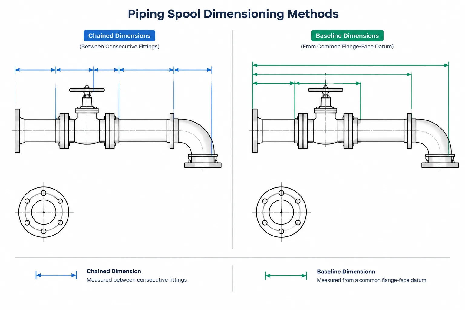
Dimensioning a piping assembly is not merely a matter of reporting CAD geometry. The dimension layout tells the fabricator and installer which relationships matter, which references remain fixed, and where unavoidable variation may be absorbed.
This guide compares piping dimension chains with baseline dimensions from a practical fit-up perspective. It explains how datum selection, overall dimensions, interface control, and planned adjustment can help turn an exact model into a drawing that communicates realistic fabrication and installation intent.
A piping model can be geometrically exact while the fabricated and installed system still requires adjustment. Pipe, fittings, welds, flanged joints, equipment nozzles, and structural interfaces each introduce real-world variation. How dimensions are organized determines where that variation accumulates and whether installers can identify the dimensions that truly control fit-up.
Two common approaches are chained dimensioning and baseline dimensioning. Neither method is universally correct. The practical objective is to select stable reference points, expose critical interfaces, and avoid dimension schemes that imply more control than fabrication or field conditions can provide.
What Is a Piping Dimension Chain?
A dimension chain is a sequence of adjacent measurements. Each dimension begins where the preceding one ends. Along a straight spool, for example, a drawing might dimension from a flange face to an elbow centerline, from that elbow to a branch centerline, and from the branch to the opposite end connection.
This approach follows the physical order of components and can make a drawing easy to read. It is particularly useful when a fabricator needs individual cut lengths, fitting locations, or weld-to-weld relationships.
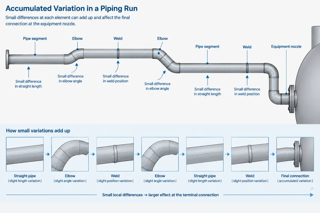
The limitation is that each manufactured, cut, assembled, and welded segment can contribute variation. The final position at the end of a long chain depends on the combined result of all preceding segments. A CAD system may calculate the chain perfectly, but it does not eliminate shop or field variation.
What Is Baseline Dimensioning?
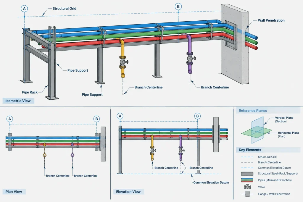
Baseline dimensioning measures multiple features from a shared datum rather than from one another. The datum might be an equipment nozzle face, column grid, structural centerline, vessel centerline, floor elevation, established plant coordinate, or another controlled project reference.
For example, the centerlines of several branches may each be located from the same flange face. If one branch is positioned slightly differently during fabrication, that difference does not redefine the drawing location of every branch after it.
Baseline dimensions are especially useful when the location of a feature relative to an external interface matters more than its distance from the neighboring fitting.
Chained and Baseline Dimensions Compared
| Consideration | Chained dimensions | Baseline dimensions |
|---|---|---|
| Reference method | Each feature is located from the preceding feature | Multiple features are located from one common datum |
| Typical strength | Shows sequential component and fabrication relationships clearly | Preserves the relationship of important features to a stable reference |
| Main risk | Variation can accumulate toward the end of the chain | The drawing can become crowded if too many dimensions share a datum |
| Useful applications | Cut-length development, local fitting spacing, and weld sequence information | Nozzle interfaces, branch locations, supports, penetrations, and coordinate control |
| Interpretation concern | The final overall result may not be directly controlled | The local distance between adjacent components may need to be derived or separately shown |
Why Accumulated Variation Matters
A dimension chain is often discussed in terms of tolerance stack-up, but piping adds several practical sources of variation that are not always represented by a simple mathematical tolerance:
- Pipe ends may be cut, beveled, faced, or threaded as separate operations.
- Fittings have manufacturing variation even when they conform to the applicable dimensional basis.
- Weld preparation, root gaps, alignment, and shrinkage affect the completed assembly.
- Flange faces and bolt-hole orientation must be controlled during fit-up.
- Equipment nozzles, steelwork, sleeves, and existing piping may not be exactly where an early model assumed.
- Field measurements may use different physical surfaces or centerlines than the original design reference.
When every intermediate distance is chained, the accumulated result appears at the last connection. That may be manageable at an open field-fit end, but it is a serious coordination concern when the chain terminates at a fixed nozzle, penetration, or prefabricated module.
Selecting a Useful Datum
A datum should be identifiable, stable, and available to the people who must use it. A convenient CAD origin is not automatically a useful fabrication or installation datum.
Equipment interfaces
For equipment connections, a nozzle face, nozzle centerline, or established equipment centerline may provide a useful reference. The chosen point must agree with the equipment drawing and project convention. Designers should not assume that a modeled equipment envelope represents verified vendor geometry.
Plant and structural references
Column grids, floor elevations, platform steel, and plant coordinates can help locate piping in the facility. However, a structural grid is not necessarily a fabrication datum for an individual spool. The drawing should make the relationship clear rather than mixing coordinate and fabrication dimensions without explanation.
Existing facilities
In retrofit work, the best datum may be a surveyed flange face, pipe centerline, wall penetration, or equipment nozzle. Its reliability depends on how it was measured and whether the physical feature can be identified in the field. Existing geometry should be marked as verified, assumed, or requiring confirmation according to project procedures.
Use Overall Dimensions to Check the Chain
An overall dimension can reveal the functional result of several intermediate dimensions. On a spool between two flanged interfaces, the face-to-face length may be more important to installation than the individual distances between internal fittings.
That does not mean every drawing should show both every chain dimension and every possible overall dimension. Duplicate dimensions can conflict after a revision. Instead, the drawing team should identify which dimensions control fabrication, which control installation, and which are reference information.
If an overall dimension is critical, it should not be left merely as the unmarked sum of a long chain. Conversely, if individual cut lengths are derived from controlled geometry and fitting takeoffs, repeating them as independent controlling dimensions can overconstrain the drawing.
Avoid Closed Dimension Loops
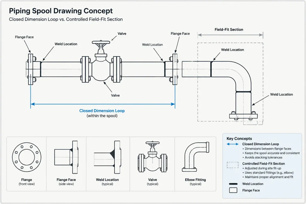
A closed dimension loop occurs when every segment in a geometric loop is dimensioned as though each value independently controls the result. In an exact CAD model, the values may agree. On a fabricated assembly, however, small variations mean all dimensions cannot necessarily be achieved independently.
A practical drawing normally leaves one relationship derived, identifies it as reference, or places adjustment at a planned location. The correct treatment depends on the project’s drafting, fabrication, and tolerance practices.
Closed loops are particularly risky around rectangular routing, equipment pairs, penetrations, and prefabricated assemblies where several fixed interfaces compete for control.
Where to Place Adjustment
If real-world variation is expected, it should be managed intentionally rather than allowed to appear at an arbitrary weld or nozzle. Depending on the design and project requirements, adjustment may be accommodated through:
- a designated field-fit spool or trim length;
- a closure weld located with suitable access;
- a removable flanged section;
- a surveyed final connection;
- a planned sequence in which one end is fitted after adjacent work is installed.
These are coordination strategies, not automatic permissions to alter dimensions. Any field adjustment must remain consistent with the piping specification, engineering requirements, inspection plan, and approved fabrication procedure.
Dimensioning Different Piping Features
Branches
Branch centerlines are often best located from a meaningful spool or plant datum, especially when they must align with equipment, instruments, supports, or parallel headers. Local spacing between branches may also be needed when congestion is the primary concern.
Supports
Support locations should relate to the reference used by structural and installation teams. Dimensioning every support from the previous fitting can obscure its relationship to steelwork. The CAD model should also distinguish the nominal support location from field-adjustable details where applicable.
Penetrations
Wall, floor, and platform penetrations are coordination interfaces. Their locations are commonly more useful when referenced to grids, elevations, or established coordinates than when chained through several fittings. The opening size and sealing arrangement are separate controls from the pipe centerline location.
Flange faces
Flange face planes provide clear assembly interfaces, but the model and drawing must identify which face is being referenced. Gasket representation, joint gaps, and mating component geometry can otherwise cause different users to measure from different planes.
A Practical CAD Review Workflow
- Identify fixed interfaces. Mark equipment nozzles, existing tie-ins, penetrations, module boundaries, and other points that cannot move freely.
- Choose stable datums. Use references that can be found in the model, drawing, shop, or field.
- Trace each dimension chain. Determine where variation will accumulate if every segment differs slightly from nominal geometry.
- Confirm the controlling result. Decide whether the important value is a face-to-face length, branch coordinate, support position, centerline elevation, or local cut length.
- Remove conflicting redundancy. Avoid presenting derived and controlling dimensions as though both independently govern fabrication.
- Plan adjustment deliberately. Do not allow the last fixed nozzle in a chain to become the accidental fit-up point.
- Check drawing consistency. Compare isometrics, spool drawings, equipment drawings, structural references, and model coordinates.
- Record verification status. Clearly separate verified field or vendor information from preliminary model assumptions.
Choosing the Right Method
Chained dimensions are valuable for communicating local fabrication relationships. Baseline dimensions are valuable for preserving locations relative to critical references. Most effective piping drawings use a controlled combination of both.
The key question is not simply, “Which method is standard?” It is, “Which physical relationship must remain correct when manufacturing, welding, surveying, and installation variation are introduced?” Once that relationship is identified, the dimension scheme can support the actual fabrication and fit-up strategy instead of merely describing perfect CAD geometry.
Applying the Dimension Strategy During Drawing Review
A useful review separates geometric completeness from functional control. A drawing can contain enough dimensions to recreate the modeled shape yet still fail to communicate the interface that must fit. Reviewers should therefore ask what each dimension is intended to control and who will use it.
Distinguish controlling and reference information
If a dimension governs fabrication or installation, its role should be consistent with the project drafting procedure. A derived dimension may help readers check geometry, but it should not appear to compete with the dimension that establishes the required interface. This distinction becomes especially important when an overall length and its component dimensions appear together.
Review from the fixed interface backward
Instead of reading only in the direction of fabrication, begin at the least adjustable connection and trace the geometry backward. This approach often reveals whether a long chain places accumulated variation at an equipment nozzle, existing tie-in, penetration, or other constrained location.
Check whether the datum is usable outside CAD
A model origin, construction point, or hidden centerline may be mathematically convenient but difficult to identify in the shop or field. A practical datum should correspond to a clearly defined physical feature or an established project reference. The drawing should also make clear which surface, plane, axis, or centerline is intended.
Coordinate the adjustment strategy with the drawing
If the installation plan depends on field verification, trimming, or a closure connection, the dimension scheme should not imply that every adjoining segment is independently fixed. Fabrication notes, weld designation, spool boundaries, inspection requirements, and installation sequencing should support the same strategy.
Key Editorial Takeaway
Dimension chains describe local relationships effectively, while baseline dimensions protect important locations from being redefined by preceding segments. The strongest piping drawings use each method where it communicates physical control most clearly. The final selection should reflect verified interfaces, fabrication sequence, access, inspection needs, and the approved method for managing variation.
Frequently Asked Questions
Are baseline dimensions always better for piping drawings?
No. Baseline dimensions are helpful when several features must remain related to a common datum. Chained dimensions may communicate cut lengths, fitting spacing, or weld-to-weld relationships more directly. Many drawings need a deliberate combination of both methods.
Why can an exact CAD dimension chain still create fit-up problems?
CAD reports nominal geometry without reproducing every manufacturing, welding, surveying, and installation effect. Variation introduced along adjacent segments can accumulate at the end of the chain, particularly when the terminal connection is fixed.
What makes a good piping datum?
A good datum is stable, clearly identified, relevant to the controlled interface, and accessible to the people using the drawing. Examples may include a defined flange face, equipment centerline, structural reference, surveyed tie-in, or established plant coordinate.
Should an overall dimension be shown with chained dimensions?
It may be appropriate when the overall result controls fit-up or provides necessary verification. However, the drawing should distinguish the controlling value from derived or reference information so that redundant dimensions do not create conflicting requirements.
What is the main problem with a closed dimension loop?
A closed loop can imply that every segment and the overall result must be achieved independently. Real fabrication variation may make that impossible. A relationship generally needs to remain derived, be identified as reference, or be accommodated through an approved adjustment strategy.
Where should accumulated variation be managed?
Variation should be directed toward a planned and approved adjustment location rather than an accidental fixed interface. The selected approach must remain consistent with the piping specification, engineering requirements, inspection plan, and fabrication procedure.
Can a CAD origin serve as the fabrication datum?
Only when it corresponds to a reference that fabricators and installers can reliably identify. An arbitrary digital origin may be useful for model coordination without being suitable as a physical measurement reference.