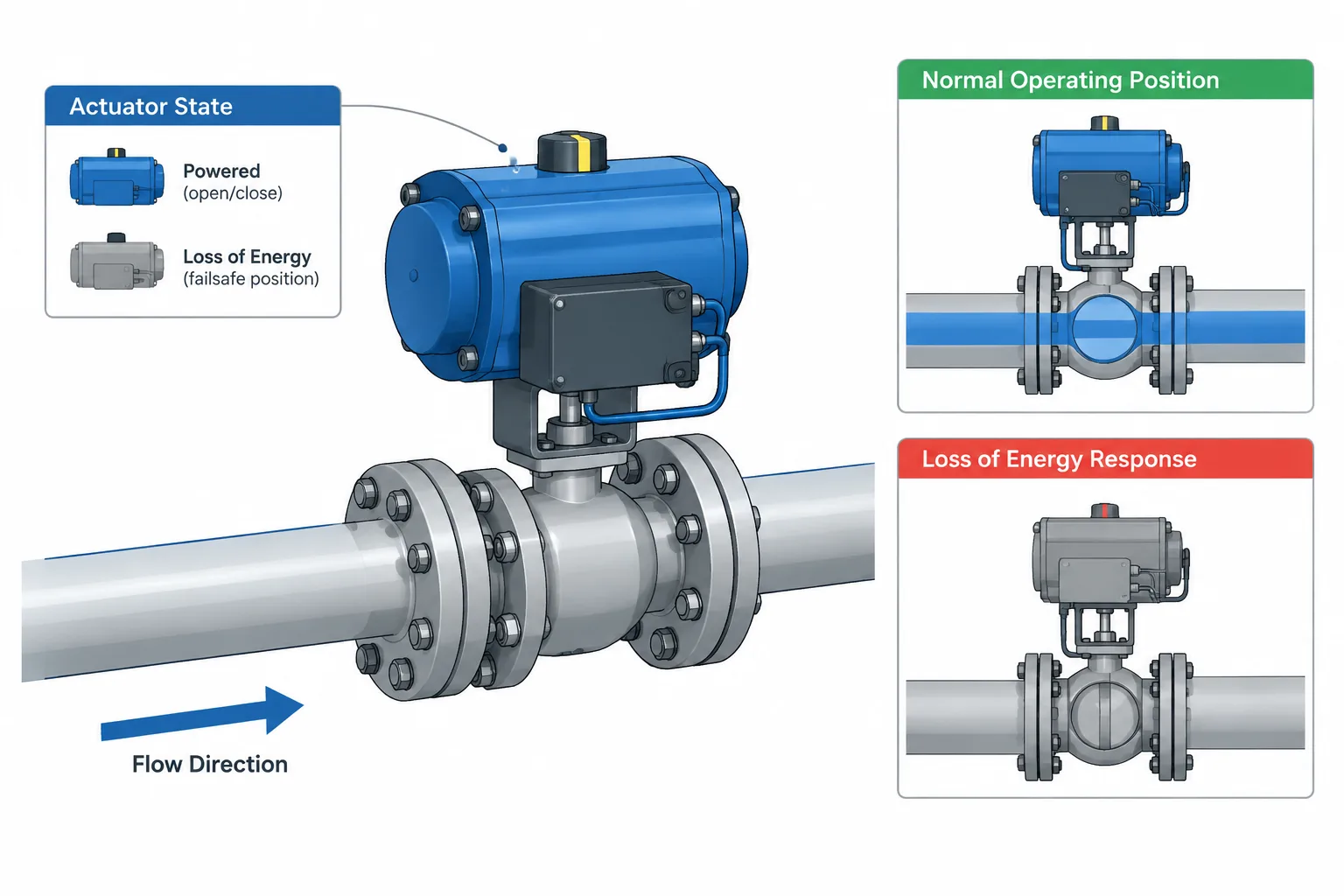
Valve normal position vs. fail position is a documentation distinction, not simply a choice between open and closed. Normal position refers to a defined operating mode, while fail position refers to the intended response to a specified loss of power, signal, or motive energy.
When reviewing a valve tag, read each state as a separate attribute. Then verify the applicable operating mode, failure event, actuator arrangement, and administrative controls. The guide below shows how these attributes relate without treating them as interchangeable.
A valve can be shown as normally open, fail closed, and locked open without those descriptions contradicting one another. Each term answers a different question about how the valve is expected to behave or be managed. Confusing these states can lead to incorrect P&IDs, unsuitable actuator arrangements, misleading equipment lists, and operating errors.
The distinction is especially important when information moves between process engineering, instrumentation, piping design, CAD models, procurement documents, and plant procedures. A 3D valve model may show physical geometry and operator orientation, but it does not automatically communicate the valve’s normal operating state or its response to a loss of power.
This guide explains the major valve-state terms and provides a practical workflow for keeping them coordinated.
Normal Position Describes the Intended Operating Condition
A valve’s normal position is generally the position expected during the defined normal operating condition of the process. Common descriptions include:
- Normally open: The valve is expected to remain open during normal operation.
- Normally closed: The valve is expected to remain closed during normal operation.
- Normally throttled: The valve normally operates at an intermediate position rather than fully open or fully closed.
The word “normal” requires context. A plant can have startup, shutdown, standby, regeneration, cleaning, test, and emergency modes in addition to steady operation. A valve that is open during production may be closed during standby. The project should therefore define which operating mode establishes the documented normal position.
Normal position is an operating designation, not necessarily a description of the symbol’s drawn geometry. Many P&ID symbol conventions do not depict a manual valve disc or ball in its actual operating position. The state may instead be conveyed by a note, abbreviation, tag attribute, database field, or accompanying legend.
Fail Position Describes Response to a Defined Failure
The fail position describes the intended final position of an actuated valve after loss of a specified source of motive energy or control. Typical terms are:
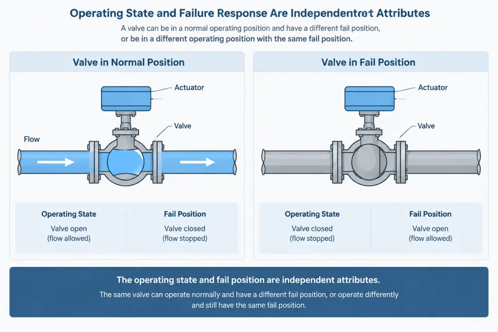
- Fail open: The actuator arrangement drives or permits the valve to move toward open when the defined failure occurs.
- Fail closed: The valve moves toward closed.
- Fail in place: The valve is intended to remain near its last position, subject to actuator behavior, leakage, process forces, and stored energy.
- Fail to a designated position: A modulating valve may be arranged to move to a specified intermediate state rather than a fully open or closed endpoint.
A fail designation is incomplete unless the failure being considered is understood. Loss of instrument air, electrical power, hydraulic pressure, control signal, or communications can produce different outcomes depending on the actuator, accessories, control architecture, and available stored energy.
For example, the response to loss of a control signal may not be identical to the response to loss of actuator power. A positioner, solenoid valve, accumulator, spring-return actuator, or control-system command can influence the result. The P&ID abbreviation should not be treated as a substitute for the complete control and actuator definition.
Normal and Fail Positions Are Independent Descriptions
Normal position and fail position should not be combined mentally into one attribute. A valve may have any technically appropriate pairing selected by the process and safety design.
| Documented condition | Question it answers | Example interpretation |
|---|---|---|
| Normally open | Where is the valve during the defined normal operating mode? | The process normally flows through the valve. |
| Normally closed | Where is the valve during the defined normal operating mode? | The flow path is normally isolated. |
| Fail open | Where should the valve move after the specified failure? | The selected safe response requires an open flow path. |
| Fail closed | Where should the valve move after the specified failure? | The selected safe response requires isolation. |
| Fail in place | What should happen if motive energy or signal is lost? | The valve is intended to retain its last position rather than travel to an endpoint. |
A normally open valve can also be fail closed. During ordinary operation it remains open, but the defined failure causes it to close. Conversely, a normally closed valve can be fail open if the required failure response is to establish flow.
The correct pairing depends on process consequences. Designers should not assume that closing is always the safer action. Cooling, relief, purge, minimum-flow, or protective circulation functions may require a flow path to remain open. The selected state must come from the applicable process, control, and hazard evaluation.
De-Energized Position Is Not Always the Same as Fail Position
The de-energized position describes the condition of a device when electrical, pneumatic, or hydraulic energy is removed from a particular component. This term is frequently applied to solenoid valves and actuator circuits.
It can help explain the fail action, but the two concepts are not automatically identical. Removing power from a solenoid may vent one actuator port, block another, or shift a pilot circuit. The process valve’s resulting movement depends on the complete actuator and accessory arrangement.
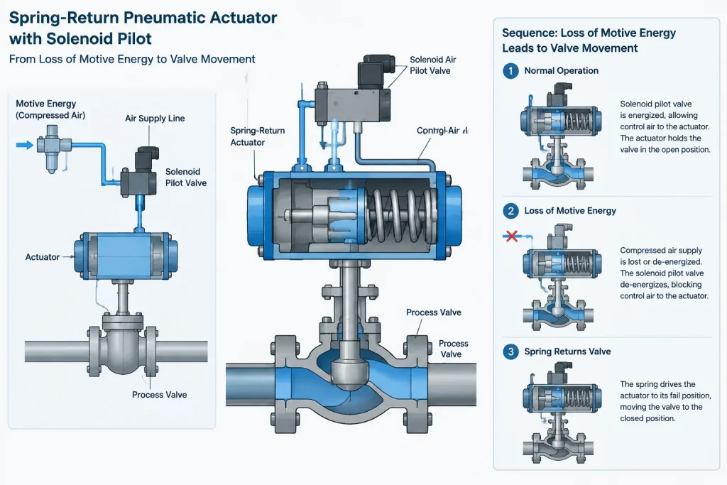
For documentation, identify which component is energized and what loss condition is being evaluated. Statements such as “de-energized to trip” or “energized to close” can be misunderstood if they do not clearly distinguish the solenoid state from the final process-valve position.
Locked and Car-Sealed Positions Describe Administrative Control
Locked open and locked closed indicate that a valve is physically secured in a required position using an established locking method. Car-sealed open and car-sealed closed similarly indicate controlled positioning, usually with a seal that reveals or restricts unauthorized operation.
These designations differ from normal position:
- Normal position describes expected process operation.
- Locked or car-sealed position describes how the required state is administratively or physically controlled.
- Fail position describes actuator response to a defined failure.
A manual isolation valve may be normally open and locked open, but it has no actuator fail position. An actuated valve can have a fail position while also being subject to operating restrictions, although the physical and procedural arrangement must not prevent its required protective action.
Locking and sealing requirements should be coordinated with operating procedures and valve accessibility. A CAD model showing a handwheel does not prove that the valve can be reached, locked, inspected, or operated safely.
Manual Valves and Check Valves Need Different Treatment
Manual valves
A manual valve does not normally receive a fail-open or fail-closed actuator designation because it has no powered actuator that moves it upon loss of motive energy. It may still be identified as normally open, normally closed, locked, or car sealed.
A gearbox does not by itself make a valve actuated. It provides mechanical advantage but still relies on manual operation unless a powered operator is fitted.
Check valves
A check valve responds automatically to flow direction and differential pressure. Describing it simply as normally open or normally closed can obscure its actual function. Documentation should identify its flow direction and type, while recognizing that disc position depends on service conditions and valve construction.
The flow arrow associated with a check valve or other directional component is not a normal-position indicator. It communicates permitted or intended flow direction.
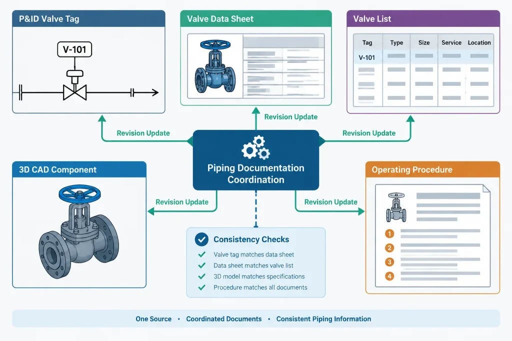
What the P&ID, CAD Model, and Data Sheets Should Control
No single project document necessarily contains every valve-state attribute. A reliable workflow assigns clear responsibility to each deliverable.
| Deliverable | Typical valve information | Key limitation |
|---|---|---|
| P&ID | Valve function, tag, actuation, normal state, fail action, interlock context, and special status notes | Symbol appearance alone may not communicate every state |
| Valve or instrument data sheet | Valve type, actuator action, accessories, power source, signal behavior, and required failure response | Must remain aligned with the current process intent |
| Line list or valve list | Service and selected valve attributes used for reporting or checking | Fields can become stale if updates are not synchronized |
| 3D CAD model | Body geometry, end connections, operator type, orientation, access envelope, and tag association | Static geometry usually does not prove operating or fail state |
| Operating procedure | Required positions for startup, normal operation, shutdown, isolation, and maintenance | Procedural state may vary by operating mode |
A valve should not be modeled with a handwheel merely because the generic library component uses one. If the design requires a pneumatic, electric, or hydraulic actuator, the model should represent enough of that assembly to support space, access, weight, and removal reviews. The control attributes should then remain connected to the same valve tag in project data.
A Practical Coordination Workflow
- Define the operating mode. State what “normal” means for the project or system.
- Record the normal position. Identify whether the valve is open, closed, or regulating during that mode.
- Define the initiating failure. Distinguish loss of signal, instrument air, electrical power, hydraulic pressure, or another event.
- Specify the required final response. Determine whether the valve should open, close, remain in place, or move to another defined position.
- Verify the hardware arrangement. Confirm that the actuator, spring action, solenoid circuit, positioner, and accessories can provide the intended response.
- Coordinate project documents. Compare the P&ID, valve list, data sheet, control narrative, cause-and-effect information, and CAD model.
- Check physical layout. Review actuator clearance, manual override access, local indication, tubing or cable approach, and maintenance removal space.
- Control revisions. When process intent changes, update all affected documents rather than modifying only the P&ID note.
Common Documentation Errors
- Assuming a valve drawn open on a schematic is formally designated normally open.
- Using “fail safe” without stating the required valve position and initiating failure.
- Assigning fail closed to every shutdown valve without evaluating process consequences.
- Giving a manual valve an actuator fail designation.
- Confusing a solenoid’s de-energized state with the process valve’s final position.
- Treating flow direction, normal position, and fail position as the same attribute.
- Changing actuator action on a data sheet without updating the P&ID and control documentation.
- Modeling the valve body while omitting an actuator that creates a significant access or clash envelope.
Key Takeaway
Normal position explains where a valve is expected to be during a defined operating mode. Fail position explains where an actuated valve should move after a specified failure. Locked and car-sealed states describe position control, while de-energized state describes the condition of a particular powered component.
These attributes are related, but they are not interchangeable. Clear definitions, tag-based data coordination, and verification of the actual actuator arrangement are necessary to carry process intent correctly from the P&ID into procurement, CAD layout, commissioning, and operation.
How to Review a Valve-State Record
A useful valve-state review begins with process intent rather than symbol appearance. The reviewer should be able to trace each designation to a defined condition and confirm that the hardware and project documents support the same result.
- Identify the operating case: Confirm which production, standby, startup, shutdown, or maintenance condition establishes the normal position.
- Name the failure event: Avoid recording a fail action without identifying the loss of signal, power, pressure, or other initiating condition being evaluated.
- Separate device states: Distinguish the process valve position from the state of its actuator, solenoid, positioner, or control output.
- Check physical feasibility: Confirm that actuator action, stored energy, accessories, process forces, and mechanical restraints are consistent with the intended response.
- Compare tag-based records: Review the P&ID, data sheet, valve list, control description, operating procedure, and CAD model under the same valve tag.
- Resolve conflicts explicitly: Do not select one document as correct merely because it is newer or more detailed. Refer the discrepancy to the responsible engineering disciplines and record the approved resolution.
What CAD Review Can and Cannot Confirm
A piping model can help verify actuator orientation, access, removal space, local indication, manual override access, and routing around the valve assembly. These checks are important because the selected actuator and accessories may occupy substantially more space than a generic valve body.
However, static geometry does not establish normal position, fail action, or control logic. Those attributes should be maintained in controlled project data and connected to the valve tag. If model properties include state fields, they should mirror approved engineering information rather than assumptions made by the modeler.
Use Precise Review Comments
Comments such as check valve position or confirm fail safe are too broad for effective coordination. A useful comment identifies the valve tag, the conflicting attributes, the operating or failure condition involved, and the documents that require reconciliation. This makes the issue actionable without presuming the engineering decision.
Frequently Asked Questions
Can a valve be normally open and fail closed?
Yes. The valve can remain open during the defined normal operating mode and move closed when the specified failure occurs. The descriptions answer different questions.
Does a normally closed valve require a fail-closed actuator?
No. Normal position does not determine actuator fail action. The required response must be selected from the process, control, and hazard evaluation for the defined failure.
Does the P&ID symbol show the actual valve position?
Not necessarily. Symbol geometry may identify valve type or function without depicting the operating position. Consult the project legend, notes, tag attributes, and controlled valve data.
Is a de-energized solenoid state the same as the process valve fail position?
Not automatically. The solenoid may vent, block, or redirect the actuator circuit. The process valve response depends on the complete actuator, pilot, positioner, accessory, and energy arrangement.
Should a manual valve have a fail-open or fail-closed designation?
Ordinarily, no actuator fail action applies when there is no powered actuator. A manual valve can still have a normal position and may be locked or car sealed in a required state.
What should a drafter do when valve-state documents conflict?
Flag the discrepancy against the valve tag and identify the affected documents. Do not infer the correct state from model geometry, a generic symbol, or an isolated note. The responsible process, instrumentation, piping, and operations personnel should reconcile the approved intent.