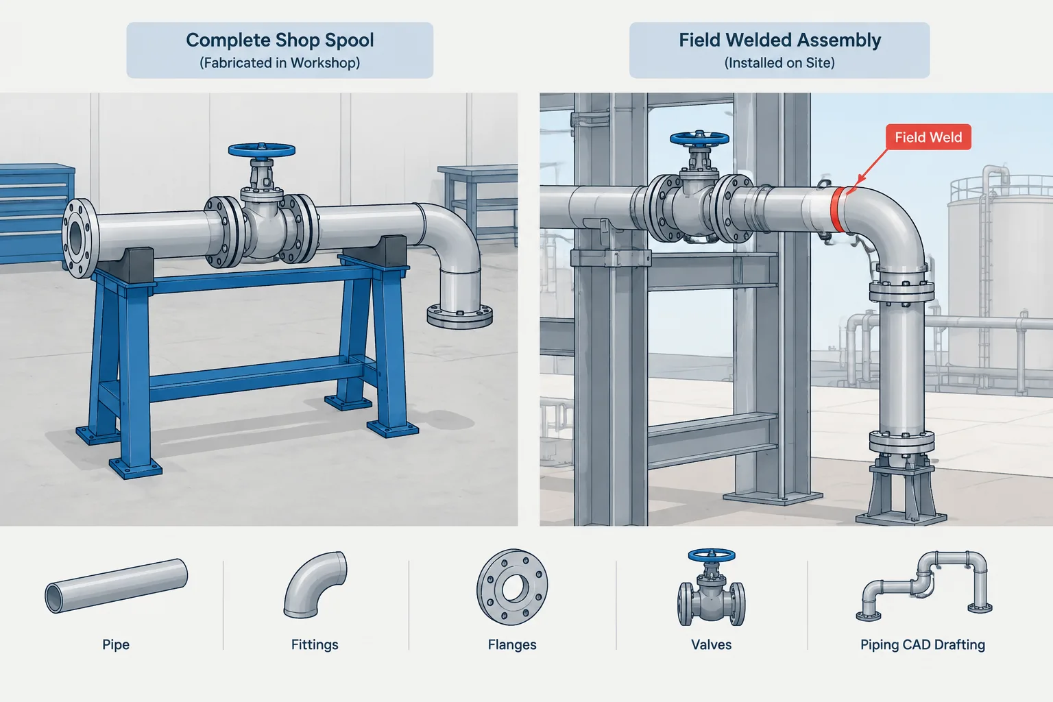
Field weld vs. shop weld in piping CAD is both a construction-planning decision and a data-control issue. The designation influences spool ownership, fabrication scope, erection sequence, joint accessibility, and the consistency of isometrics, spool drawings, and weld reports.
This guide explains how to evaluate weld location without confusing a physical joint with a drawing split or assuming that every spool boundary requires welding. Use it as a practical review framework, then apply the project’s approved specifications, fabrication procedures, construction plan, and drawing conventions.
The distinction between a field weld and a shop weld may look like a simple drawing note, but it affects how piping is divided, fabricated, transported, installed, inspected, and tracked. A weld placed in the wrong category can create an impractical spool, an inaccessible site joint, or a mismatch between the CAD model and the fabrication plan.
For designers and drafters, the important question is not merely where a weld symbol appears. It is whether the proposed joint can be completed in the intended location under realistic fabrication and construction conditions. The field-versus-shop decision should therefore be coordinated with spool boundaries, transport limits, installation sequence, access, and project execution requirements.
What Is a Shop Weld?
A shop weld is a welded joint intended to be completed in a fabrication facility before the piping assembly is delivered to the installation site. It commonly joins pipe, fittings, flanges, branch components, and other weld-end items into a fabricated spool.
Shop fabrication generally offers controlled working conditions, established handling equipment, repeatable fit-up practices, and easier access for fabrication and inspection activities. These advantages do not mean that every joint should automatically become a shop weld. The resulting spool must still be transportable, liftable, dimensionally manageable, and installable.
In CAD and spool documentation, shop welds usually lie within a single fabricated assembly. They help define the internal construction of that assembly but do not necessarily mark where one spool ends and another begins.
What Is a Field Weld?
A field weld is intended to be completed at the installation site. It often joins two fabricated spools, connects new piping to existing piping, closes a run that must be assembled around equipment or structure, or accommodates installation sequencing.
A field weld designation describes the planned place of execution. It does not, by itself, define the welding process, examination requirement, acceptance criteria, or joint quality. Those requirements come from the applicable project documents, piping specification, procedures, and governing code.
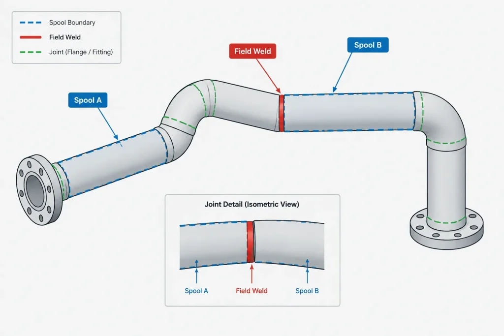
Field welding can introduce conditions that are less predictable than shop fabrication. Access may be limited, surrounding components may already be installed, and environmental or operating constraints may affect the work. Consequently, the location selected in the model should provide a joint that can actually be aligned, welded, inspected, and, when required, repaired.
Field Weld vs. Shop Weld at a Glance
| Consideration | Shop weld | Field weld |
|---|---|---|
| Work location | Fabrication facility | Installation site |
| Typical role | Builds components into a spool | Connects spools or closes site-installed piping |
| Working conditions | Generally more controlled | Dependent on site access and conditions |
| Dimensional purpose | Establishes fabricated spool geometry | May support installation sequence or field adjustment |
| CAD significance | Usually contained within a spool | Often associated with a spool boundary or site interface |
| Primary planning checks | Fabrication access, handling, and spool size | Welding access, fit-up, inspection, and erection sequence |
These are typical distinctions rather than universal rules. Project terminology and fabrication practices should be checked before issuing drawings or data.
Why Not Every Spool Boundary Is a Field Weld
A spool boundary identifies where one fabricated or managed assembly ends and another begins. The physical connection at that boundary might be welded, flanged, threaded, grooved, or another permitted joint type. Therefore, a spool break should not automatically be represented as a field weld.
Conversely, a field weld often creates a practical spool boundary because the adjoining pieces will arrive separately. The relationship should be explicit in the project data rather than inferred from graphics alone.
This distinction matters when generating isometrics, material takeoffs, weld lists, and spool sheets. A system that treats every drawing split as a physical break can create false joints. A system that ignores intended field welds can produce oversized or impossible-to-install spools.
Selecting a Practical Field-Weld Location
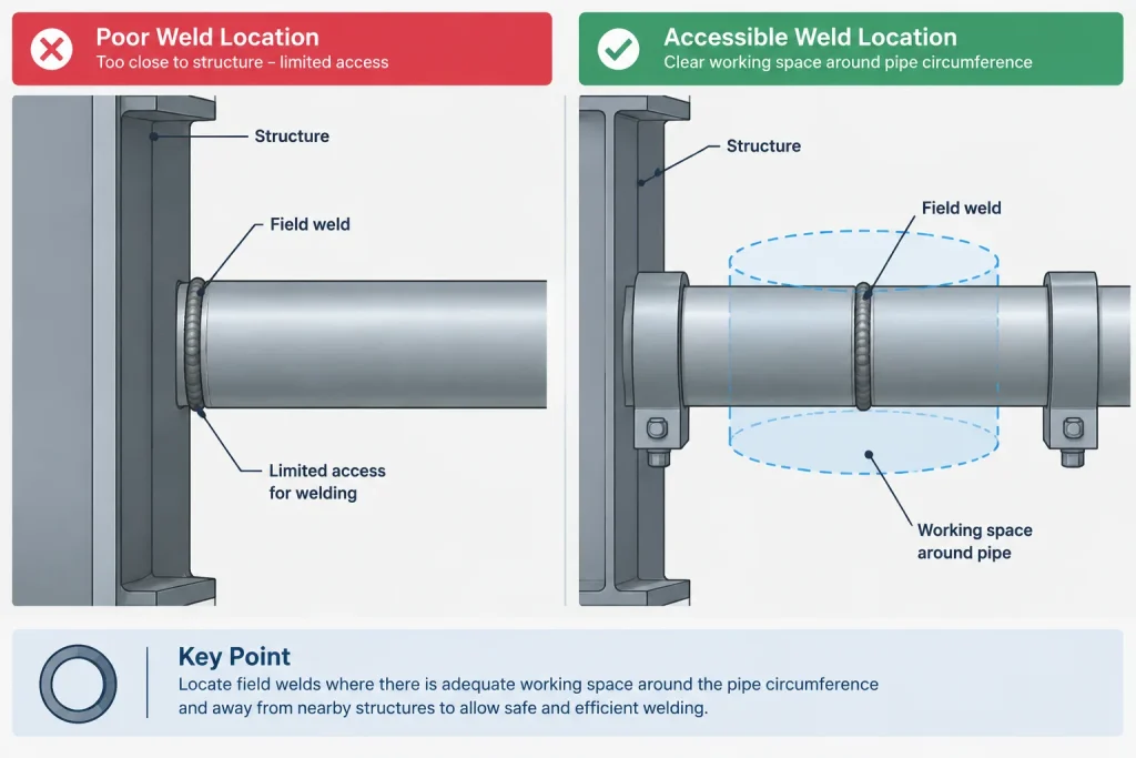
A field weld should be located by considering the work around the entire joint, not only the pipe centerline. A visually open location in plan may be obstructed above, below, or behind the pipe.
Provide access around the circumference
The installer needs meaningful access to prepare, align, weld, and examine the joint as applicable. Walls, floors, structural members, cable trays, adjacent pipes, insulation, and equipment can restrict that access. A joint should not be placed where only one side is reachable unless the selected construction method has been specifically reviewed.
Avoid congested component zones
Placing a field weld immediately beside a flange, valve body, branch connection, support attachment, or fitting can complicate fit-up and work access. Available straight pipe, component geometry, weld separation requirements, and project fabrication rules must be evaluated rather than assumed.
Consider spool movement during installation
The two sides of a field joint must be brought into alignment. If both assemblies are fully restrained before closure, there may be no practical way to move them into position. The model review should consider lifting, rotation, insertion, temporary support, and the order in which surrounding joints are completed.
Check inspection and repair access
Access needed for welding is not always the same as access needed for examination or repair. The selected location should be reviewed for the project’s intended inspection method without assuming that a clear visual line is sufficient.
Field Fit Welds and Closure Joints
Some projects distinguish a normal field weld from a field fit weld or closure weld. The latter may indicate that final pipe length, end preparation, or alignment will be established using verified site conditions. Terminology varies, so the meaning should be defined in the project drafting or fabrication procedure.
A field fit designation should not become a substitute for incomplete design. The drawing should still establish the intended route, component arrangement, connection points, and controlling references. It should also make clear which piece is expected to be adjusted and which dimensions remain fixed.
Extra material, trim allowance, or adjustment length must not be invented by the drafter. If such an allowance is required, it should come from the responsible engineering, fabrication, or construction authority and be documented consistently.
How to Represent Weld Responsibility in CAD
A dependable CAD workflow stores weld responsibility as component or joint data instead of relying only on a drawn symbol. This allows drawings, weld lists, spool records, and reports to use the same controlled designation.
Useful joint information may include:
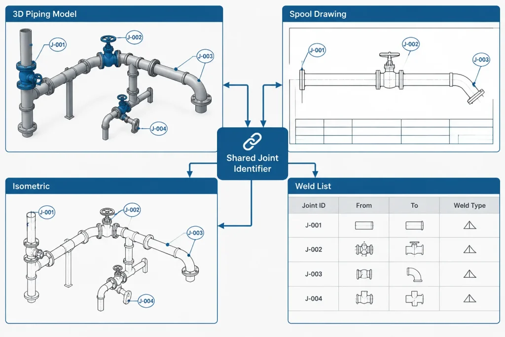
- A unique weld or joint identifier.
- Planned shop, field, or field-fit status.
- The connected components or pipe segments.
- Associated line and spool identifiers.
- Joint type and end-preparation references where required.
- Drawing or isometric ownership.
- Revision and status information.
The CAD model should not be treated as the final authority for welding procedure or acceptance. Its purpose is to communicate geometry, location, connectivity, and execution intent while maintaining coordination with controlled project documents.
Isometric and Spool Drawing Presentation
Field welds should be recognizable on the deliverable used for installation. Depending on project practice, that may involve a specific symbol, note, identifier, or data-generated annotation. The legend must clearly differentiate a field weld from a shop weld and from nonwelded break points.
A useful drawing also makes the joint location dimensionally understandable. The installer should be able to determine which adjoining spool or component owns each side of the connection. Avoid placing the apparent field-weld mark at a convenient annotation location if the modeled joint is elsewhere.
Shop drawings should show enough information to fabricate each spool without accidentally including material assigned to an adjacent spool. Isometrics and spool sheets should agree on weld identifiers, break locations, and component ownership.
Common Coordination Errors
- Using a field-weld symbol only as a graphic: Reports and regenerated drawings may not recognize the joint status.
- Placing the joint inside an inaccessible area: The centerline fits, but welding and inspection access do not.
- Confusing a drawing break with a physical joint: Splitting an isometric sheet does not necessarily divide the pipe.
- Creating an oversized shop spool: The model is geometrically continuous but cannot be transported or erected as one assembly.
- Leaving both sides fully restrained: The field joint has no practical fit-up movement.
- Changing spool limits without updating weld data: Drawings, weld lists, and material reports no longer agree.
- Treating every field weld as adjustable: A normal field joint is not automatically a field-fit allowance.
A Practical Review Workflow
- Identify the intended fabrication and construction strategy for the line.
- Divide the routing into realistic fabricated assemblies.
- Check spool handling, transport, lifting, and installation paths.
- Assign physical connection types at each spool boundary.
- Locate field welds where alignment and circumferential access are practical.
- Review nearby structure, supports, insulation, equipment, and other disciplines.
- Confirm whether any joint requires a separately defined field-fit status.
- Generate isometrics, spool drawings, and weld reports from coordinated data.
- Compare joint identifiers and ownership across deliverables before issue.
- Control later changes through the project revision process.
Key Takeaway
The difference between a field weld and a shop weld is fundamentally about where the joint is planned to be completed, but its consequences extend through the entire piping workflow. The designation affects spool definition, installation sequence, access, drawing presentation, and data reporting.
A strong CAD model does more than mark a weld. It places the joint where the work can realistically occur, associates it with the correct spools, and keeps that intent consistent across isometrics, fabrication documents, and construction information. Final joint requirements must always be verified against the applicable project specifications and execution procedures.
Drawing Control Through Design Changes
Weld responsibility should remain coordinated when routing, component placement, support locations, or spool limits change. Moving a break point graphically without updating the underlying joint record can leave the model, isometric, spool sheet, material assignment, and weld list describing different construction scopes.
A controlled revision should verify the joint location, connection type, connected components, spool ownership, identifier, and planned execution location. If a joint changes from shop to field work, or from field to shop work, the affected deliverables should be regenerated or reviewed rather than corrected independently with disconnected notes.
Questions for a CAD and constructability review
- Is the marked location a real physical joint or only a drawing division?
- Do the connected items belong to the intended fabrication and installation scopes?
- Can the fabricated assemblies be handled and brought into their installed positions?
- Is there practical access for fit-up, welding, examination, and possible repair?
- Can either side move as needed during alignment, or are both sides restrained?
- Does the joint status match across the model, isometric, spool drawing, and reports?
- Is any field-fit intent clearly distinguished from an ordinary field weld?
- Are project-specific symbols, notes, and identifiers used consistently?
Responsibility Versus Technical Requirements
The shop-or-field attribute identifies where the work is intended to occur. It should not be used as shorthand for weld process, joint preparation, examination, acceptance, or inspection responsibility. Those requirements must remain tied to the applicable controlled documents.
This separation is important in CAD databases. A joint can retain its geometric and spool relationships while other approved attributes are managed through their proper engineering and quality-control workflows. Keeping these concepts distinct reduces ambiguous annotations and helps prevent drafting assumptions from becoming unintended fabrication instructions.
Practical Handoff Between Teams
The most reliable result comes from coordination among piping design, fabrication, construction, inspection, and project controls. Designers establish a workable location and connectivity; fabricators confirm spool practicality; construction personnel review erection and access; and document-control processes keep issued information aligned.
CAD output should communicate execution intent clearly, but it does not replace field verification or approved project procedures. Existing conditions, installation constraints, and later design changes may require formal review before the planned joint location is accepted for construction.
Frequently Asked Questions
Does every spool boundary require a field weld?
No. A spool boundary separates fabrication or management scope, while the physical connection may be welded or may use another permitted joint type. The connection must be defined explicitly rather than inferred from the spool break.
Is every field weld also a field-fit weld?
No. A field weld identifies the intended work location. A field-fit or closure designation may indicate that site verification or adjustment is expected, but its exact meaning depends on the project procedure.
Can a field-weld symbol be added only to the isometric?
A symbol may communicate the designation visually, but relying on graphics alone can create inconsistencies. Where the CAD system supports it, the joint status should be stored as controlled data used by drawings and reports.
What should be checked before selecting a field-weld location?
Review access around the joint, spool movement, alignment, nearby components, structure, supports, insulation, inspection needs, repair access, and installation sequence. The centerline appearing clear is not sufficient by itself.
Can a drawing split create a weld?
No. Dividing an isometric or placing information on another sheet does not automatically create a physical break in the piping. Connectivity and joint data should determine whether a weld exists.
Who decides whether a weld is shop or field work?
The designation should follow the project’s approved design, fabrication, and construction responsibilities. A drafter should not assign or change execution responsibility solely for drawing convenience.