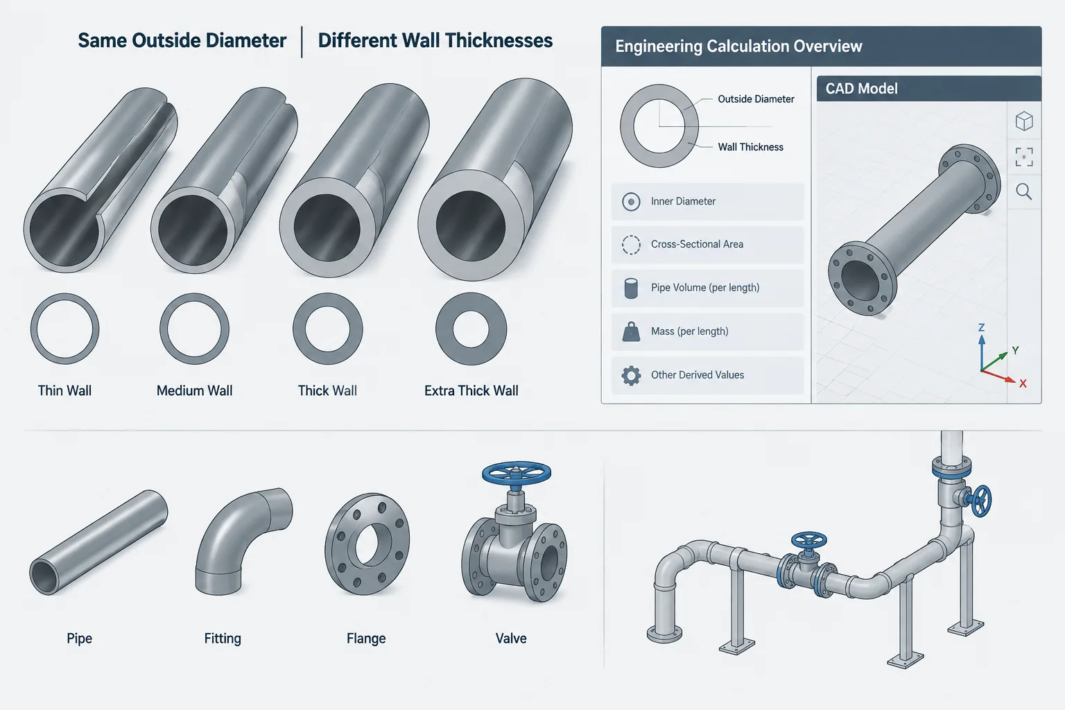
Required pipe wall and selected pipe schedule belong to the same design workflow, but they represent different stages of that workflow. The required wall comes from an engineering evaluation of the design basis. The selected schedule or nominal wall identifies the approved product that will be specified, purchased, modeled, and reported.
This guide explains how that decision moves from calculation records into piping specifications and CAD data. It also highlights the checks needed when a schedule selection affects bores, component interfaces, material reports, supports, or downstream design documents.
A pipe wall-thickness calculation and a pipe schedule selection are related, but they are not the same decision. The calculation establishes the wall needed to satisfy defined design conditions and governing rules. The selected schedule identifies a commercially recognized nominal wall thickness for the chosen pipe size and material specification.
This distinction matters because CAD models, line lists, piping specifications, and bills of material usually carry the selected schedule rather than every intermediate calculation value. A model may therefore show Schedule 40, Schedule 80, or another designation without revealing why that schedule was selected or how much design margin remains. Designers and drafters need to understand the handoff so they do not mistake a database label for an engineering calculation.
Calculated Wall and Selected Wall Answer Different Questions
The required wall answers an engineering question: what minimum thickness is needed for the specified design basis after applying the rules relevant to that system? The selected nominal wall answers a procurement and geometry question: which available pipe product provides an acceptable wall while remaining compatible with the piping material specification and connected components?
The calculation may consider pressure, temperature, pipe outside diameter, material strength basis, joint-related factors, allowances, and other code- or service-dependent inputs. The exact equation and treatment of each input depend on the governing piping code, project criteria, material, manufacturing route, and service conditions.
The result of that process is not automatically a schedule. It is first compared with available pipe wall thicknesses permitted by the project piping specification. The engineer then selects an acceptable product designation. That selection may be influenced by more than pressure containment, including mechanical robustness, corrosion expectations, threading or grooving needs, standardization, availability, and compatibility with fittings or valves.
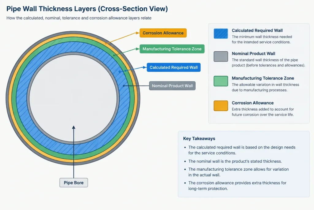
Key Wall-Thickness Terms
| Term | Practical meaning | Where it is commonly controlled |
|---|---|---|
| Pressure design thickness | The thickness produced by the applicable pressure-design relationship before some additional allowances are considered. | Engineering calculation |
| Required thickness | The design minimum after the applicable allowances and calculation rules have been addressed. | Calculation record and design criteria |
| Corrosion or erosion allowance | Additional wall reserved for expected material loss during service, when required by the design basis. | Line list, piping class, corrosion study, or calculation |
| Mechanical allowance | Wall assigned for material removed or weakened by features such as threads, grooves, or other mechanical details where applicable. | Component design and piping specification |
| Nominal wall thickness | The stated wall of the selected pipe product. It is a product designation rather than a guarantee that every measured point equals that exact value. | Dimensional reference and purchase description |
| Minimum permitted product wall | The lower wall condition allowed after applicable product tolerances are considered. | Product specification and engineering verification |
| Measured wall thickness | The wall found by physical inspection or testing at a particular location. | Inspection and condition assessment records |
These terms should not be collapsed into a single generic field called “thickness.” Without a qualifier, users may not know whether a value represents a calculation result, nominal product dimension, minimum acceptance limit, or field measurement.
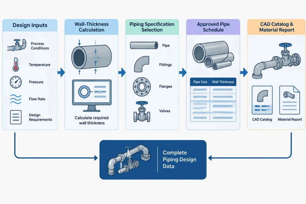
How the Selection Process Typically Works
Establish the design basis
The responsible engineer first confirms the governing code, design pressure and temperature, material basis, pipe size, service conditions, and project-specific criteria. Changes to any of these inputs can affect the required wall.
Calculate the design requirement
The applicable calculation method is used to establish the pressure-related thickness and incorporate required allowances or adjustment factors. Because calculation structures vary, a CAD user should not attempt to reconstruct the result from schedule and line-list data alone.
Account for product tolerance
Pipe is purchased by nominal wall thickness, but manufacturing specifications may permit variation from that nominal value. The selected product must remain adequate when the applicable negative wall tolerance is handled in the manner required by the governing rules and project criteria.
This is one reason simply choosing the first nominal wall greater than a calculated number can be wrong. The comparison must be made on a consistent basis by the responsible engineer.
Choose an available wall designation
The required result is compared with pipe products allowed by the piping material specification. A schedule designation may be selected where that system applies, while some products may instead be ordered by an explicit nominal wall thickness. Schedule numbers are not universal thickness values across all nominal pipe sizes.
Check the complete piping class
The pipe wall selection must fit the broader material class. The class may also control fitting construction, branch connections, flange type, valve ends, gasket selection, bolting, and joining methods. A heavier pipe schedule does not automatically increase the rating of every component in the line.
What Should Appear in the CAD Model?
The CAD model should generally carry the approved design selection, not an unofficial recreation of the engineering calculation. Depending on the project data structure, useful properties may include:
- Nominal pipe size or DN designation
- Selected schedule or nominal wall description
- Material specification and grade reference
- Piping class or specification identifier
- Service or line-number association
- Insulation or lining data where relevant to geometry
- Design-status, hold, or verification indicators
Calculated required wall, corrosion allowance, and remaining design margin may be maintained in calculation software, line lists, specification databases, or engineering records rather than embedded in every CAD object. If these values are added to the model, their meaning, units, source, and revision status must be clearly defined.
The modeled pipe bore should also be treated carefully. A generic CAD catalog may derive inside diameter from nominal outside diameter and nominal wall. That is useful for representation and interference checking, but it does not describe local manufacturing variation, corrosion, lining irregularity, or measured field condition.
Schedule Changes Can Affect More Than the Pipe
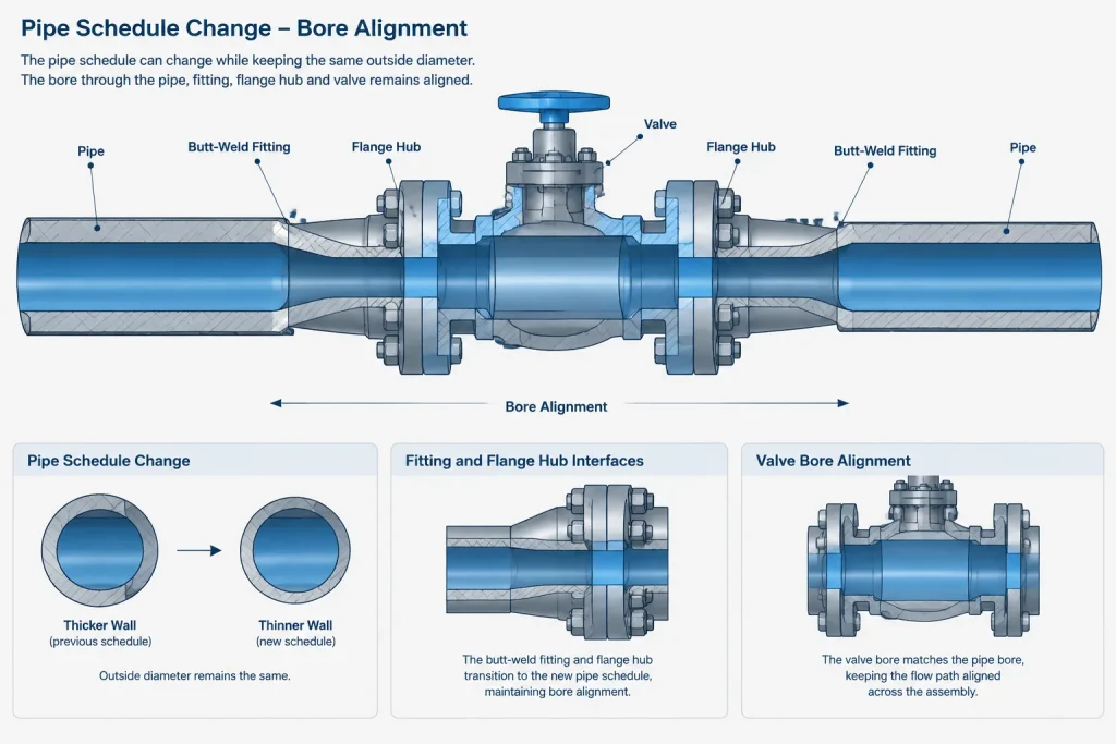
For a given nominal pipe size within a dimensional system, changing schedule commonly changes the nominal wall and therefore the nominal inside diameter while leaving the standardized outside diameter unchanged. This allows many external components to connect around a consistent pipe OD, but it does not eliminate all interface concerns.
A schedule change should trigger review of:
- Butt-weld bore alignment with fittings, valves, and flange hubs
- Socket-weld compatibility and permitted pipe insertion
- Threading suitability and remaining wall
- Branch outlet and reinforcement assumptions
- Flow area and hydraulic calculations
- Pipe weight and support loads
- Availability under the approved material specification
- Catalog part mappings and material takeoff descriptions
Reducers, fittings, and valves may use their own dimensional or rating designations. Their acceptability cannot be inferred from the pipe schedule name alone.
Common Handoff Errors
Treating schedule as a pressure rating
A schedule identifies a wall series; it is not a standalone pressure class. Pressure suitability depends on material, temperature, dimensions, design rules, allowances, and other factors.
Assuming a calculated wall is the purchase wall
A calculation result is normally converted into an available nominal product selection. Placing the raw required value in a bill of material can create an unavailable or ambiguous purchase description.
Ignoring the source of catalog data
A CAD catalog may contain a schedule-to-wall mapping, but that mapping does not prove the schedule is approved for the line. The piping specification remains the controlling selection source.
Changing schedule only to solve a graphics issue
A designer should not change schedule merely to make bores align visually or to match a convenient catalog component. Bore mismatches must be evaluated using the approved components and appropriate fabrication detail.
Copying a schedule across a specification break
A line may retain the same nominal size while changing material class, corrosion allowance, joining method, or design conditions. Schedule must be checked on both sides of the specification boundary rather than propagated automatically.
A Practical CAD Review Checklist
- Confirm that the model schedule matches the current piping class and line data.
- Verify that the schedule is valid for the specific nominal size and material product.
- Check that connected fittings and valve ends use compatible bores and joining details.
- Review specification breaks, reducers, branches, and equipment nozzle interfaces.
- Confirm that model properties distinguish nominal wall from calculated or measured wall.
- Regenerate material reports after an approved schedule change.
- Recheck weights, supports, flow calculations, and fabrication drawings where affected.
- Record the engineering source or change reference instead of relying on an unexplained manual edit.
Keep Engineering Basis and CAD Selection Connected
The safest workflow preserves a clear relationship between the wall-thickness calculation, approved piping specification, selected pipe product, and CAD catalog entry. Engineering determines what is required. The piping class defines what may be used. CAD documents the approved selection and coordinates its geometry with the rest of the system.
Understanding required pipe wall versus selected schedule helps prevent false assumptions about pressure capability, bore size, product tolerance, and component compatibility. It also makes schedule changes easier to review because the team can distinguish an engineering decision from a database or drafting update.
Managing the Calculation-to-CAD Handoff
A reliable handoff depends on traceability rather than duplicating the full wall calculation inside the model. The schedule stored on a CAD object should be linked through project controls to the approved piping class, line data, and engineering basis. This lets designers use the correct geometry and purchase description without treating the model as the calculation authority.
Define which document controls each value
Project teams should distinguish the sources for required wall, corrosion or erosion allowance, selected nominal wall, piping class, and measured field thickness. If the same property appears in several systems, the controlling source and update method should be understood. Otherwise, an outdated catalog value can conflict with a revised line list or piping specification.
Use clear property names
A model field labeled only thickness is open to interpretation. Property names should indicate whether the entry is nominal, calculated, minimum permitted, or measured. Units, revision status, and data origin should also be available wherever the value may be used for engineering or fabrication decisions.
Treat manual overrides as controlled changes
Manually replacing a catalog schedule can break the relationship between the modeled part, purchase description, connected components, and material report. If an override is necessary, it should follow the project change process and identify the engineering authorization behind it.
Review downstream effects before publishing
An approved schedule change may require more than updating a pipe property. The team should determine whether the change affects fitting selection, valve or flange bore transitions, branch details, support loading, hydraulic data, fabrication information, and material takeoffs. Relevant outputs should then be regenerated from the updated source.
A Useful Decision Hierarchy
- Engineering basis: Establishes the design conditions, governing rules, material basis, and required wall.
- Piping specification: Defines which pipe products and connected components are permitted.
- Approved selection: Identifies the schedule or nominal wall to be used for the line.
- CAD catalog: Maps the approved selection to model geometry and component records.
- Project deliverables: Communicate the selection through drawings, line lists, reports, and bills of material.
If these layers disagree, the conflict should be resolved through engineering and document control. A convenient catalog entry should not silently replace the approved design selection.
Frequently Asked Questions
Is required pipe wall the same as nominal wall thickness?
No. Required wall is an engineering result based on the applicable design basis and allowances. Nominal wall is the stated thickness of the selected commercial pipe product.
Can pipe schedule be used as a pressure rating?
No. Schedule describes a wall series or product designation. Pressure suitability also depends on material, temperature, dimensions, allowances, governing rules, and the complete piping assembly.
Should the calculated required wall be entered into the CAD catalog?
Usually the catalog should represent the approved product selection. A calculated value may be stored elsewhere or included as a controlled reference property, but its meaning and source must be clearly distinguished from nominal catalog geometry.
Why can selecting the next nominal wall above the calculated value be insufficient?
The comparison must account for the governing calculation method, applicable allowances, product tolerance, material specification, and project criteria. The responsible engineer must make the comparison on a consistent basis.
Does changing pipe schedule require connected components to change?
Not automatically, but it requires review. The change may affect bore alignment, joining details, branches, hydraulic calculations, weight, supports, catalog mappings, and material descriptions.
What should a drafter do when the line list and CAD catalog show different schedules?
Do not resolve the conflict by assumption. Confirm the current piping specification, line data, revision status, and engineering approval, then update the model through the project change process.