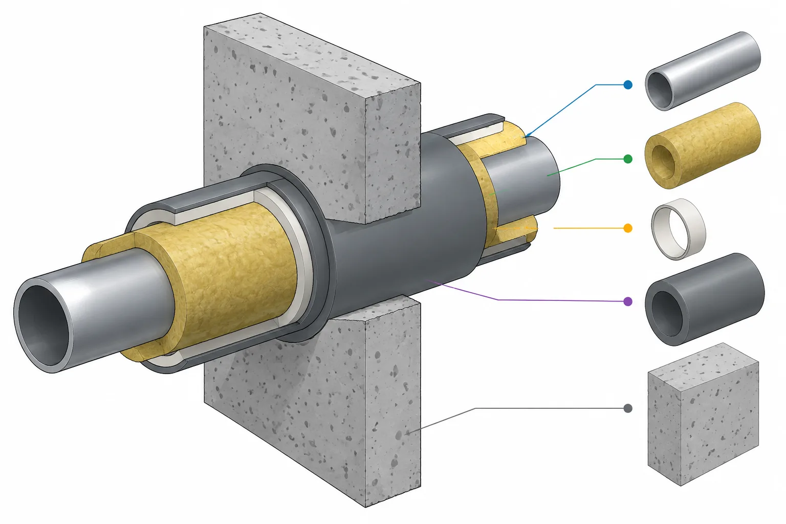
Piping penetrations in CAD should be treated as coordinated interfaces rather than simple cuts through walls, floors, roofs, or foundations. The pipe route establishes where the service crosses the construction, but it does not independently determine the sleeve, opening, clearance, or sealing assembly.
This guide explains how to represent penetration components separately, coordinate their functional requirements, and issue opening information without turning preliminary geometry into an unverified construction detail.
A pipe passing through a wall, floor, roof, foundation, or equipment enclosure creates more than a circular hole. The penetration may need space for insulation, movement, installation tolerances, sealing systems, fire-resistance requirements, waterproofing, or a structural sleeve. It also creates an interface between piping, structural, architectural, civil, and specialty disciplines.
For CAD designers, the main challenge is separating the pipe geometry from the opening and from the penetration assembly. These are related objects, but they do not necessarily have the same diameter, material, location tolerance, or responsible party. A clean model and drawing set should communicate each part without implying that an unverified generic detail is suitable for construction.
Pipe, clearance envelope, and opening are different
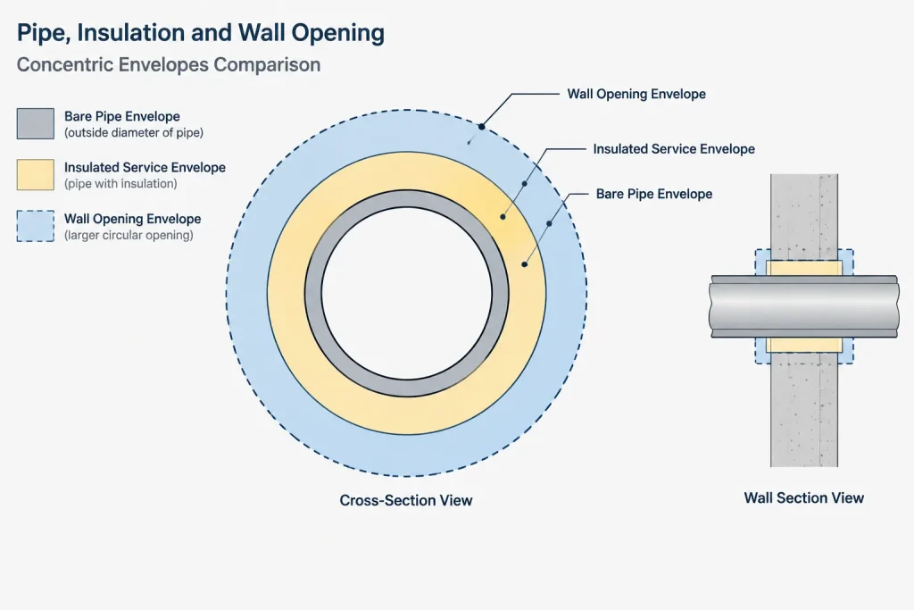
The modeled pipe outside diameter is only the starting point for a penetration. A useful coordination model distinguishes at least three envelopes:
- Pipe envelope: The actual outside surface of the pipe or piping component.
- Service envelope: The space occupied by insulation, jacketing, heat tracing, coatings, or another applied system.
- Opening envelope: The sleeve, core-drilled hole, formed opening, or blockout required in the wall or slab.
The opening cannot be selected reliably from nominal pipe size alone. Pipe outside diameter, insulation requirements, movement, seal configuration, installation method, and project tolerances can all affect the required opening. Where a proprietary sealing assembly is used, its verified product data may control the acceptable pipe and opening range.
Flanges, couplings, valve bodies, branch fittings, and removable insulation covers also deserve attention. A penetration sized for straight pipe may not allow a nearby enlarged component to be installed, removed, or pulled through the opening.
Sleeves, core holes, and blockouts
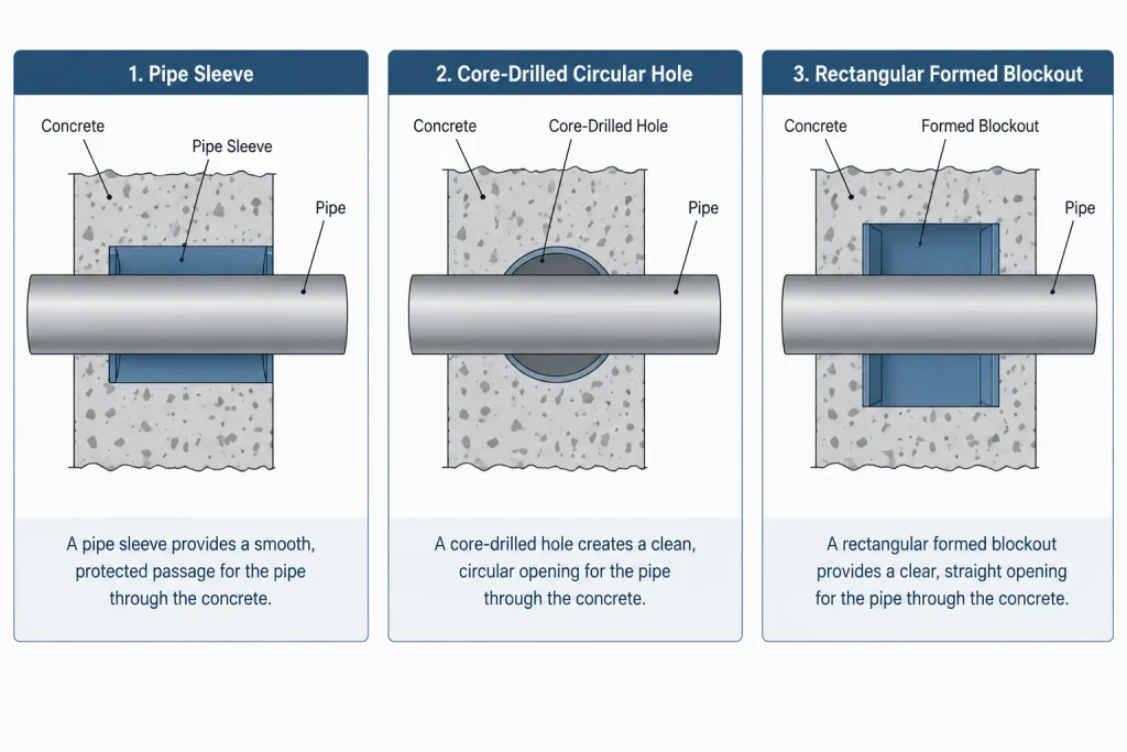
Drawings often use the words sleeve, core hole, and opening loosely, but they describe different construction conditions.
Pipe sleeves
A sleeve is a separate element placed through the wall or floor. Depending on the design, it may remain in the construction and provide a defined surface for a seal, protect the opening edge, or assist installation. The sleeve material, wall thickness, length, end projection, coating, anchorage, and sealing interface must come from the applicable project detail or specification.
Core-drilled holes
A core hole is cut through completed concrete or masonry. Its location must be coordinated with reinforcement, embedded items, structural restrictions, and concealed services. Showing a core hole in CAD does not establish that drilling is structurally acceptable. Approval and field scanning requirements remain project-specific.
Formed openings and blockouts
A formed opening or blockout is reserved before concrete placement or wall completion. It may be rectangular even when the eventual pipe and seal are circular. Blockouts can provide installation flexibility, but their final closure and sealing need to be defined. A blockout should not be represented as a finished penetration assembly unless the closure construction is known.
| Item | What CAD should communicate | Typical coordination concern |
|---|---|---|
| Pipe | Centerline, outside envelope, size reference, service, and slope where applicable | Routing and connection geometry |
| Insulation or covering | Required outer envelope and any local termination or removable section | Clearance and continuity |
| Sleeve | Identifier, nominal geometry, limits, and source detail | Material, installation, and seal compatibility |
| Core hole | Opening identifier, location, elevation, and size source | Existing reinforcement and field conditions |
| Blockout | Width, height, depth or wall extent, and reference coordinates | Formwork and final closure |
| Seal assembly | Type reference and responsible specification or detail | Fire, water, gas, movement, and environmental performance |
Annular space and sealing intent
The annular space is the region between the outside of the penetrating item and the inside of the sleeve or opening. In simple plan or section views it appears as a ring, but its purpose varies. It may accommodate a mechanical seal, packing, firestop system, flexible weather seal, grout, or another specified assembly.
Designers should avoid filling this region with a generic hatch and labeling it simply as “sealant” unless that is the verified project requirement. A seal intended to resist water is not automatically a firestop system, and a fire-resistance detail is not automatically designed for pressure, movement, or exterior weather exposure. Some penetrations require more than one coordinated function.
The item passing through the opening must also be identified correctly. A seal may interface with bare pipe, a sleeve, a casing, or an approved insulation or jacket system. If insulation stops at the wall, the drawing should show where it terminates. If insulation continues through, its compatibility with the specified penetration assembly must be confirmed.
Movement can control penetration geometry
A pipe centerline may not remain in its modeled installation position. Thermal growth, support movement, vibration, settlement, seismic displacement, or equipment movement can shift the pipe relative to the wall or floor. A penetration that clears the cold-position pipe may interfere during another operating condition.
When movement is relevant, the CAD model should not merely enlarge the opening without explanation. Document the basis for the clearance and identify the controlling movement information. The penetration seal must also be capable of accommodating the expected displacement; geometric clearance alone does not establish seal performance.
Supports near the penetration require deliberate review. An anchor, guide, or line stop can change how movement is transferred to the opening and adjacent structure. Conversely, an unintended tight penetration can act as an unplanned restraint. Penetration review should therefore be coordinated with the support arrangement and, where applicable, the piping flexibility assessment.
Sloped and skewed penetrations
A pipe crossing a wall at an angle does not create the same geometry as a pipe perpendicular to the wall. The apparent opening on the wall face becomes elongated, and the path through a thick wall is longer. Similar issues occur when a sloped pipe passes through a horizontal floor.
In 3D CAD, model the actual route through the full wall or slab thickness rather than checking only one face. Review clearance at both faces and through the middle of the construction. A circular sleeve may still be used in some designs, but its axis, length, and end treatment must match the approved penetration concept.
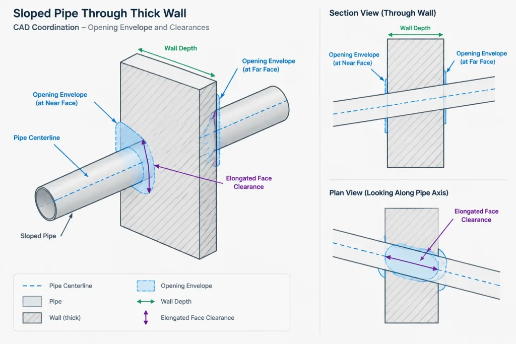
Dimensions should establish the pipe or opening from a controlled datum. Relying on a visually projected circle in an oblique view can obscure the true location. Sections normal to the penetration axis are useful for understanding annular space, while architectural or structural sections show its relationship to the host construction.
What to include in a penetration schedule
Large projects benefit from assigning each coordinated opening a unique identifier. A penetration schedule can connect model objects, drawings, discipline reviews, and field installation records. Useful fields may include:
- Penetration or opening ID;
- Associated line number, service, or system;
- Host wall, floor, roof, or structure reference;
- Pipe size reference and actual modeled outer envelope;
- Insulation or covering status;
- Opening type, such as sleeve, core hole, or blockout;
- Opening shape and verified dimensions;
- Center coordinates and elevation;
- Pipe slope or crossing angle;
- Seal or detail reference;
- Movement requirement or analysis reference;
- Responsible discipline and approval status;
- Field verification and as-built status.
The schedule should distinguish calculated or proposed information from approved construction information. A preliminary opening used for coordination should not silently become a released field dimension.
Recommended CAD workflow
- Model the host construction. Use the coordinated wall, slab, or roof thickness and location rather than a symbolic line whenever penetration depth matters.
- Confirm the pipe envelope. Check outside diameter, insulation, tracing, jacketing, nearby joints, and installation sequence.
- Identify functional requirements. Determine whether the interface involves fire resistance, water control, pressure, movement, hygiene, shielding, or another project-specific condition.
- Select the opening concept. Coordinate whether the design uses a sleeve, core hole, blockout, or another approved assembly.
- Create a separate opening object. Do not derive construction holes solely from a graphical pipe cut. Give the opening its own identifier and properties.
- Check movement and access. Review operating positions, support behavior, installation clearances, and component removal paths.
- Issue coordinated views and schedules. Provide dimensions from stable datums and reference the controlling detail or specification.
- Reconcile field changes. Record relocated openings, changed sleeve sizes, and actual installed conditions in the as-built workflow.
Common drafting and modeling errors
- Sizing the opening directly from NPS or DN without checking actual outer envelopes;
- Showing insulation graphically but omitting it from the clearance calculation;
- Treating a sleeve and a hole as interchangeable schedule items;
- Using a generic seal symbol without identifying its required function;
- Ignoring pipe movement or allowing the penetration to become an unintended restraint;
- Checking a skewed crossing only at one wall face;
- Locating openings from movable equipment or unfinished surfaces rather than controlled datums;
- Failing to coordinate core drilling with structural and embedded-item information;
- Deleting an opening when a pipe route changes without notifying the discipline responsible for the host construction.
A penetration is an interface, not just a void
Good penetration documentation connects piping geometry with construction, sealing, movement, and installation intent. The pipe model defines where the service passes, but it does not by itself define the required sleeve or opening. Keeping the pipe, service envelope, opening, and seal as distinct coordinated items makes revisions easier to track and reduces assumptions in the field.
Before release, verify dimensions and assembly requirements against the project specifications, approved details, structural constraints, and applicable manufacturer information. CAD can clearly represent the interface, but suitability depends on the complete reviewed design.
Managing penetration information through design changes
Penetration coordination is most reliable when geometry, responsibility, and approval status are managed together. Each opening object should remain traceable to its associated pipe, host construction, and controlling detail even when those items are maintained by different disciplines.
Separate proposed geometry from approved information
An opening created during routing may be adequate for model coordination but not ready for fabrication, forming, or field drilling. CAD properties, schedules, and drawing notes should make that distinction visible. A change in status should follow the project review process rather than being inferred from the appearance of the model.
Preserve relationships during revisions
Moving a pipe should trigger review of the related sleeve, blockout, core hole, seal, insulation envelope, and host construction. The old opening should not simply disappear from the piping model if another discipline has already incorporated it into drawings or construction information. Revision communication is part of the penetration workflow.
Use views that answer different coordination questions
- Plan and elevation views establish location from controlled datums.
- Host-construction sections show wall or slab extent, sleeve limits, and interface conditions.
- Views normal to the pipe axis clarify the relationship between the pipe, service envelope, annular space, and opening.
- Model review views help reveal conflicts with reinforcement zones, embedded items, nearby components, and access paths.
Apply a release check before construction use
Before opening information is released, confirm that the pipe route is sufficiently stable, the host location is coordinated, the outer service envelope is represented, and the opening concept has an identified design basis. Also verify that movement, installation access, sealing functions, and discipline ownership have been reviewed. This check does not replace project specifications, structural approval, fire-resistance documentation, waterproofing requirements, or verified product information.
Frequently asked questions
Is the pipe outside diameter the same as the required opening diameter?
No. The required opening may also depend on insulation, jacketing, movement, installation clearance, tolerance, and the selected seal or sleeve assembly. Nominal pipe size alone does not define the construction opening.
Should a sleeve and a core hole use the same CAD object?
They should be distinguishable even if a project uses a shared object family or block. A sleeve is an installed element, while a core hole describes an opening cut through completed construction. Their properties, responsibilities, and approval requirements can differ.
Who owns a piping penetration?
Ownership is project-specific. Piping may establish the service route and required envelope, while structural, architectural, civil, or specialty disciplines may control the host construction and assembly requirements. The model or schedule should identify responsibility rather than leave it implied.
Can a generic seal symbol be used on a drawing?
A symbol may indicate that sealing is required, but it should not imply unverified performance. Fire resistance, water control, gas control, pressure resistance, weather exposure, and movement capability are separate requirements that must be tied to the applicable reviewed detail or specification.
How should angled pipe penetrations be checked?
Review the complete crossing through the host thickness, including both faces and the interior path. A projected view at only one face can conceal reduced clearance or an elongated opening condition.
What happens when a routed pipe is moved?
The associated opening, sleeve, seal, schedule entry, host drawing, and approval status should be reviewed. If the previous opening was already issued or constructed, it also needs a documented disposition rather than silent deletion.