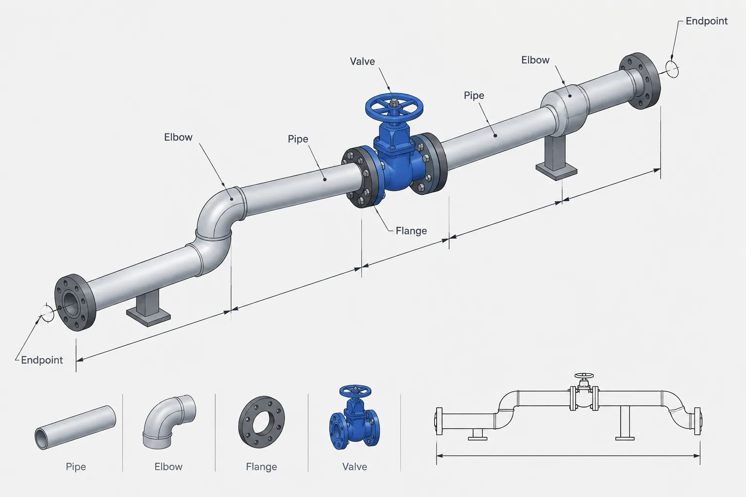
Straight pipe length between fittings cannot be determined reliably from the visible gap between CAD components. The designer must identify the actual connection endpoints, calculate the pipe segment from verified component geometry, and then confirm that the result supports fabrication, inspection, assembly, operation, and maintenance.
This guide explains how to separate geometric pipe length from functional clearance. It also highlights why instrument requirements, weld access, flange handling, valve removal, supports, insulation, and connection type must be reviewed independently rather than reduced to one universal modeling rule.
Straight pipe between adjacent fittings may look like simple connecting geometry, but its required length can be controlled by several different concerns. Welding access, instrument performance, flange assembly, fabrication methods, valve maintenance, insulation, and construction tolerances may all influence the space needed between components.
There is no single universal minimum straight pipe length that applies to every piping connection. A short segment that is practical in one welded utility line may be unsuitable near a flowmeter, lined component, field weld, or removable valve. Designers should therefore treat straight length as a functional requirement rather than as leftover space between CAD objects.
What Does Straight Pipe Length Mean?
In a piping layout, straight pipe length is the axial distance occupied by pipe between the defined ends of adjacent components. Determining that length requires knowing where each component actually terminates.
Depending on the connection, the controlling points may include:
- Elbow tangent points or fitting weld ends
- Flange faces
- Valve end faces
- Socket shoulders or insertion limits
- Threaded engagement locations
- Grooved-end preparation limits
- Equipment nozzle faces
- Vendor-defined connection points
A centerline distance alone does not reveal the available straight pipe. The takeout of each fitting must be subtracted from the controlling center-to-center or face-to-center dimension. The resulting value may represent a modeled pipe segment, but it is not automatically the final shop cut length.
Why a Very Short Pipe Segment Can Cause Problems
CAD software may permit two components to be connected by an extremely short pipe object. Physical fabrication is less forgiving. The segment still needs recognizable ends, suitable weld preparation, workable assembly sequencing, and enough room for the selected joining process.
Welding and inspection access
Adjacent circumferential welds can become difficult to prepare, weld, examine, repair, or identify when they are crowded together. The required separation depends on the component geometry, welding process, material, wall thickness, inspection method, and project rules.

The model should also account for nearby obstructions. A nominally adequate straight piece may still be inaccessible if a flange, valve body, support, structural member, or equipment casing blocks the welder or inspection equipment.
Heat effects and component limitations
Closely spaced welds can concentrate fabrication activity in a small area. Heat-sensitive linings, seals, coatings, valve internals, or specialty materials may impose additional restrictions. These limitations should come from the applicable engineering specification, approved fabrication procedure, or manufacturer information rather than from a generic CAD rule.
Cutting and end preparation
A short pipe piece must be long enough to hold, cut, bevel, measure, and fit using the fabricator’s available equipment. Even when a geometric segment can be drawn, the shop may prefer a fitting-to-fitting fabrication method, a different fitting combination, or a revised spool break.
Different Reasons for Requiring Straight Pipe
The phrase “minimum straight length” can refer to several unrelated requirements. Before changing a layout, determine which discipline or activity needs the space.
| Reason | What controls the length | What to verify |
|---|---|---|
| Weld separation | Fabrication and inspection requirements | Project specification, weld procedure, examination access, and shop capability |
| Flow measurement | Required upstream and downstream flow conditions | Instrument data, meter type, piping disturbances, and vendor recommendations |
| Valve installation | End connection, body geometry, and removal method | Face-to-face data, bolting access, operator clearance, and maintenance plan |
| Flange assembly | Joint stack-up and tool access | Bolt insertion, wrench clearance, gasket installation, and flange separation needs |
| Pipe support | Available contact or attachment area | Shoe, clamp, guide, insulation, and structural interface |
| Joining equipment | Machine or tool envelope | Welding head, threading machine, grooving tool, or field assembly method |
| Specialty component | Manufacturer installation conditions | Connection details, thermal restrictions, access, and required adjacent spool geometry |
Instrument Straight Runs Are Not Generic Pipe Rules
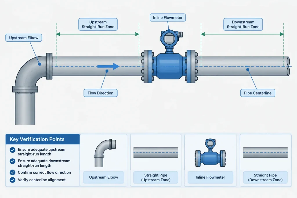
Flowmeters and some other inline instruments may require defined lengths of straight pipe upstream, downstream, or both. These lengths are intended to manage the effects of elbows, reducers, valves, branches, and other flow disturbances.
Designers should not apply a remembered rule of thumb to every meter. Requirements vary with instrument technology, installation orientation, disturbance type, pipe configuration, and vendor design. A layout that provides a long straight segment downstream but places an unsuitable disturbance immediately upstream may still be unacceptable.
In CAD, show the meter location and reserve the required straight-run envelope as early as practical. The final dimensions should be verified against approved instrument information. If a flow conditioner or vendor-supplied meter run is used, model and document it as an assembly rather than assuming it behaves like ordinary pipe.
Flanges, Valves, and Maintenance Space
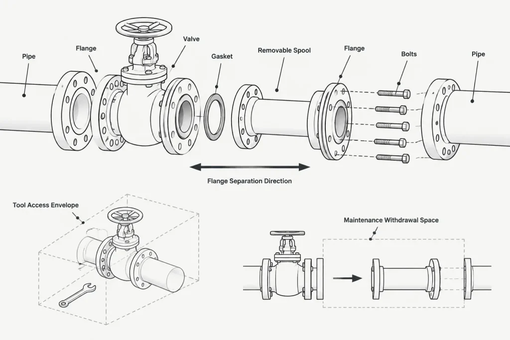
A straight spool beside a flanged valve may serve more than one purpose. It can provide room to insert bolts, spread flanges, remove a gasket, operate tools, or withdraw the valve. A connection that fits dimensionally may still be impossible to dismantle once surrounding piping is fixed.
Check the intended assembly sequence. Questions to ask include:
- Can bolts be inserted and removed without hitting the valve body or nearby steel?
- Can the flanges be separated enough to replace the gasket?
- Is there a removable spool or other means of creating axial clearance?
- Does the valve require space for internal parts to be withdrawn?
- Will insulation prevent access to fasteners or joint-separation points?
The answers may justify a longer straight section, a different spool break, or a rearranged flange location. Merely increasing the centerline spacing does not solve every maintenance problem; the added space must be placed where it supports the removal sequence.
Short Straights Between Elbows
Two elbows separated by a short straight are common in offsets and direction changes. The designer must distinguish a real straight pipe segment from fittings that meet directly at their weld ends.
If the model includes a straight segment, its length should be explicitly calculated from the fitting endpoints. Do not estimate it from the visible gap between simplified component graphics. Simplified elbows may omit wall geometry, bevels, weld gaps, or true end planes.
When the calculated segment becomes very short, consider whether the geometry should instead be represented as a fitting-to-fitting assembly. That decision must agree with the piping specification and fabricator’s intended method. It should not be created by overlapping elbow solids until the centerlines appear connected.
How Connection Type Changes the Calculation
Butt-welded connections
For butt-welded construction, cut length is commonly developed from the fitting weld-end locations, with fabrication treatment applied according to the project’s detailing method. Bevel geometry and assembly gaps should not be improvised from a generic model.
Socket-welded connections
Socket-weld layouts must account for pipe insertion into the fitting or valve socket. The visible distance between component bodies is not the pipe cut length. Approved component dimensions and the required assembly practice control the result.
Threaded connections
Threaded pipe extends into each connected component. Engagement and makeup affect the exposed length and overall assembly. A CAD model that stops pipe at the outside face of a coupling or valve will generally misrepresent the connection.
Flanged connections
Flanged components are normally located by mating faces and face-to-face or face-to-end dimensions. The straight pipe attached to a flange is controlled by the flange’s pipe-end connection, not by the mating face alone.
A Practical CAD Review Workflow
- Identify the controlling connection points. Confirm whether dimensions terminate at faces, weld ends, tangent points, sockets, or another defined location.
- Use verified component dimensions. Avoid measuring simplified symbols or unverified downloaded geometry.
- Calculate the actual straight segment. Subtract component takeouts from the controlling layout dimension.
- Classify why the straight is needed. Separate fabrication, instrument, maintenance, support, and process requirements.
- Check the assembly sequence. Review welding, bolting, gasket installation, tool access, and component removal.
- Review nearby envelopes. Include insulation, supports, structures, equipment, and temporary construction access.
- Resolve very short segments. Confirm their feasibility with the responsible piping engineer or fabricator rather than silently deleting or stretching them.
- Document the controlling dimension. Place dimensions and notes where the requirement will survive isometric extraction and drawing revisions.
Avoid Using One Global Minimum
A company may establish modeling checks that flag short pipe segments, but a warning threshold is not necessarily a universal engineering minimum. It is usually a screening tool intended to trigger review.
The most reliable approach is to preserve the reason behind each required straight length. Instrument runs should remain linked to instrument requirements; fabrication clearances should be checked against shop practice; and maintenance spaces should reflect the actual removal plan. This prevents a dimension from being copied into another context where it no longer serves its intended purpose.
Straight pipe length between fittings is therefore both a geometric and constructability issue. Accurate endpoints produce the calculation, but fabrication, operation, and maintenance determine whether the result is usable.
Model Length, Cut Length, and Working Clearance
Several different dimensions may be discussed as though they were the same straight-pipe length. Keeping them separate reduces errors during modeling, spool detailing, and fabrication review.
- Model length is the pipe segment represented between defined component endpoints in the CAD system.
- Cut length is the fabrication dimension developed using the applicable connection details and shop detailing method.
- Exposed length is the visible pipe remaining after insertion, engagement, or attachment at its ends.
- Working clearance is the usable space needed for welding, examination, bolting, tools, insulation, or removal activities.
- Process straight run is a functional piping region required for instrument or flow behavior rather than merely for component fit.
These dimensions can refer to different endpoints. A segment may be valid in the model while providing inadequate working clearance, and an exposed gap may not indicate the pipe cut length when its ends enter sockets or threaded components.
Drawing and Model Communication
A short straight should be documented from recognizable engineering reference points rather than inferred from graphical spacing. Dimensions should clearly indicate whether they apply between faces, weld ends, tangent points, centerlines, or other defined connection locations.
When a straight section exists for a special purpose, the model and associated deliverables should preserve that intent. A note or design attribute can distinguish an instrument run from a fabrication allowance or maintenance space. This helps prevent later routing changes from consuming clearance that appears optional but is functionally required.
Quality Checks Before Issuing the Layout
- Confirm that adjacent components use compatible and correctly oriented connection definitions.
- Check that fitting takeouts come from approved project data rather than visual measurements of CAD graphics.
- Look for hidden insertion, engagement, bevel, or end-preparation conditions that affect fabrication.
- Review whether insulation or nearby equipment reduces the apparent access around the pipe segment.
- Verify that supports do not occupy space reserved for joints, examination, or component removal.
- Confirm that required straight-run regions remain intact after routing and equipment changes.
- Escalate unusually short segments for engineering and fabrication review instead of adjusting component geometry informally.
A useful CAD check should identify questionable geometry without declaring every short segment unacceptable. Final acceptance depends on the connection, component, service requirements, project specifications, fabrication method, and approved vendor information.
Frequently Asked Questions
Is center-to-center spacing the same as straight pipe length?
No. Center-to-center spacing includes the takeout of the connected fittings or components. Their defined endpoints must be deducted to determine the actual pipe segment.
Can the visible CAD gap be used as the pipe cut length?
Not reliably. Simplified graphics may omit insertion, thread engagement, weld preparation, or true end planes. Cut length should be developed from verified connection geometry and the approved detailing method.
Does every pair of fittings require a separate straight pipe piece?
No. Some configurations may be fabricated as fitting-to-fitting assemblies, while others require an identifiable pipe segment. The piping specification, connection geometry, fabrication plan, and project requirements control that decision.
Why can a geometrically valid segment still be unsuitable?
The segment may leave inadequate room for welding, examination, bolting, insulation, support attachment, instrument performance, or maintenance. Geometric fit is only one part of layout acceptance.
Should CAD software automatically reject short pipe segments?
A model check can flag them for review, but it should not be treated as a universal engineering rule. The reviewer must determine why the straight is needed and which approved requirement controls it.
Who should approve an unusually short straight section?
Approval should follow the project’s responsibility structure. Input may be needed from piping engineering, fabrication, welding, inspection, instrumentation, maintenance, or the component manufacturer, depending on the concern.