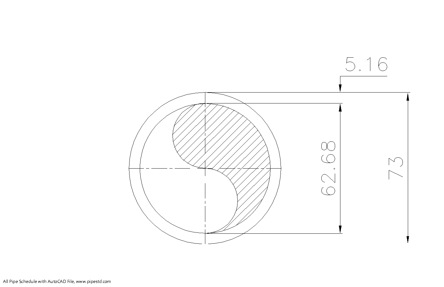
Use this page as a practical reference when identifying, modeling, estimating, or detailing 2 1/2 inch Schedule 40 pipe. The source data below brings together the NPS and DN designations, outside and inside diameters, wall thickness, and pipe weight needed for common piping and drafting tasks.
For design coordination, check the dimensional table before preparing supports, clearances, material takeoffs, or connection details. The accompanying DWG resource can also support CAD workflows, but model units, project conventions, and connection requirements should always be verified before issue.
Schedule 40 pipe 2 1/2 inch (DN65) is a standard steel pipe size commonly used in piping design, fabrication, drafting, and engineering estimation work. This page provides the standard dimensions and weight data for NPS 2 1/2 Schedule 40 pipe based on ANSI / ASME B36.10, including outside diameter, inside diameter, wall thickness, and weight per meter.
This size is widely used in industrial piping systems, utility services, water lines, and fabrication projects where accurate dimensional data is important for layout, support design, material takeoff, and installation planning.
2 1/2 Inch Schedule 40 Pipe Dimensions
- Nominal Pipe Size (NPS): 2 1/2 inch
- Diameter Nominal (DN): DN65
- Pipe Schedule: Schedule 40
- Outside Diameter (OD): 73 mm
- Wall Thickness: 5.16 mm
- Inside Diameter (ID): 62.68 mm
- Pipe Weight: 8.63 kg/m
- Pipe Weight Including Water: 11.71 kg/m
- Reference Standard: ANSI / ASME B36.10
Schedule 40 Pipe 2 1/2 Inch (DN65) Data Table
| NPS | DN | OD (mm) | Wall Thickness (mm) | ID (mm) | Weight (kg/m) |
|---|---|---|---|---|---|
| 2 1/2 inch | DN65 | 73 | 5.16 | 62.68 | 8.63 |
What Is 2 1/2 Inch Schedule 40 Pipe Used For?
2 1/2 inch Schedule 40 pipe is commonly used in industrial and utility piping systems where a standardized steel pipe size is required. Engineers, designers, and fabricators often use this size in water distribution systems, cooling water piping, industrial utility lines, process piping systems, mechanical piping layouts, and fabrication work.
Because this is a practical and widely used pipe size, accurate dimensions and weight data are important for support design, installation work, material estimation, and field coordination.
Why These Dimensions Matter in Engineering
In piping and mechanical design, standard pipe dimensions are important for more than simple identification. The outside diameter is used for supports, clamps, insulation sizing, and equipment connection layouts. The inside diameter affects internal flow area and hydraulic calculations. The wall thickness is important for fabrication, welding preparation, and pipe strength, while the pipe weight per meter is essential for support load calculations and installation planning.
Using the correct DN65 Schedule 40 pipe dimensions helps reduce drafting errors, procurement mistakes, and field fit-up problems during construction and fabrication work.
2 1/2 Inch DN65 Schedule 40 Pipe for CAD and Drafting Work
For CAD, BIM, and piping drafting work, this size is commonly listed as NPS 2 1/2 or DN65. The standard OD of 73 mm is especially useful for routing clearance, support detailing, and nozzle or equipment connection references in both 2D drawings and 3D models.
This page can be used as a quick reference for 2 1/2 inch Schedule 40 pipe dimensions, DN65 pipe dimensions, and Schedule 40 steel pipe weight per meter during design, drafting, and estimation work.
Frequently Asked Questions
What is the outside diameter of 2 1/2 inch Schedule 40 pipe?
The outside diameter of 2 1/2 inch Schedule 40 pipe is 73 mm.
What is the wall thickness of DN65 Schedule 40 pipe?
The wall thickness is 5.16 mm.
What is the inside diameter of Schedule 40 pipe 2 1/2 inch?
The inside diameter is 62.68 mm.
How much does 2 1/2 inch Schedule 40 pipe weigh?
The pipe weight is 8.63 kg/m. The weight including water is 11.71 kg/m.
Which standard covers these dimensions?
These dimensions are based on ANSI / ASME B36.10.
Conclusion
Schedule 40 pipe 2 1/2 inch (DN65) is an important reference size for industrial piping, drafting, fabrication, and engineering calculations. With an OD of 73 mm, ID of 62.68 mm, wall thickness of 5.16 mm, and weight of 8.63 kg/m, it is a useful standard pipe size for engineers, designers, and estimators working with steel piping systems.
For more pipe schedule data, compare this size with nearby standard sizes such as 2 inch and 3 inch Schedule 40 pipe pages.
How to Read the DN65 Schedule 40 Pipe Data
NPS 2 1/2 and DN65 are identification systems for the same nominal pipe size. The nominal designation should not be treated as the measured outside diameter. For physical layout and coordination, use the listed outside diameter; for flow-related checks, use the listed inside diameter and confirm the applicable design assumptions.
The wall thickness is useful when reviewing fabrication details, welded connections, and dimensional clearances. The pipe weight per meter provides a starting point for estimating and support-load coordination. The separate weight including water is a reference for a filled-pipe condition, not a complete operating load. Actual support design may also need to account for valves, fittings, insulation, fluid properties, test conditions, and the project design basis.
Practical Checks Before Using the Dimensions
- Confirm that the drawing or model uses the intended NPS and DN designation.
- Use the outside diameter when checking clamps, supports, insulation space, sleeves, and routing clearances.
- Use the inside diameter only with the relevant flow, velocity, pressure-loss, and process assumptions.
- Confirm material, end preparation, joining method, corrosion allowance, and project specification separately from the dimensional reference.
- Check whether the design condition is empty, filled, insulated, tested, or otherwise loaded before using the weight data for support coordination.
CAD, DWG, and Related Pipe References
The downloadable DWG is useful as a drafting starting point for this pipe size. Before incorporating it into a project model, review units, insertion point, layers, linework, and the way the pipe is represented in the project template. A nominal-size reference should also be coordinated with the applicable fittings, flanges, valves, supports, and equipment connection pages.
For broader comparison work, connect this reference with the site’s pipe schedule tables, Schedule 40 pipe pages, pipe weight references, flange dimensions, and nearby nominal-size pages. These related resources help readers move from a single dimensional lookup to a coordinated piping layout or material takeoff.
Additional Questions About Using This Reference
Does the nominal pipe size equal the measured outside diameter?
No. The nominal size is an identification designation. Use the published outside diameter for physical layout, support, clearance, and connection coordination.
Can the listed weight including water be used directly for support design?
It can serve as a reference for a filled-pipe condition, but support design should include the complete applicable load case. Review fluid, insulation, fittings, valves, testing, spacing, and project-specific requirements before finalizing supports.
Is the DWG ready to use without checking project settings?
The DWG is a drafting resource, but it should be checked against the project template. Confirm units, layers, insertion behavior, representation conventions, and the required connection details before issuing drawings.
What other references should be checked with this pipe page?
For a complete piping layout, compare the pipe data with the relevant fittings, flanges, valves, supports, schedule references, and adjacent nominal-size pages. Dimensional compatibility should be confirmed for the actual project components.