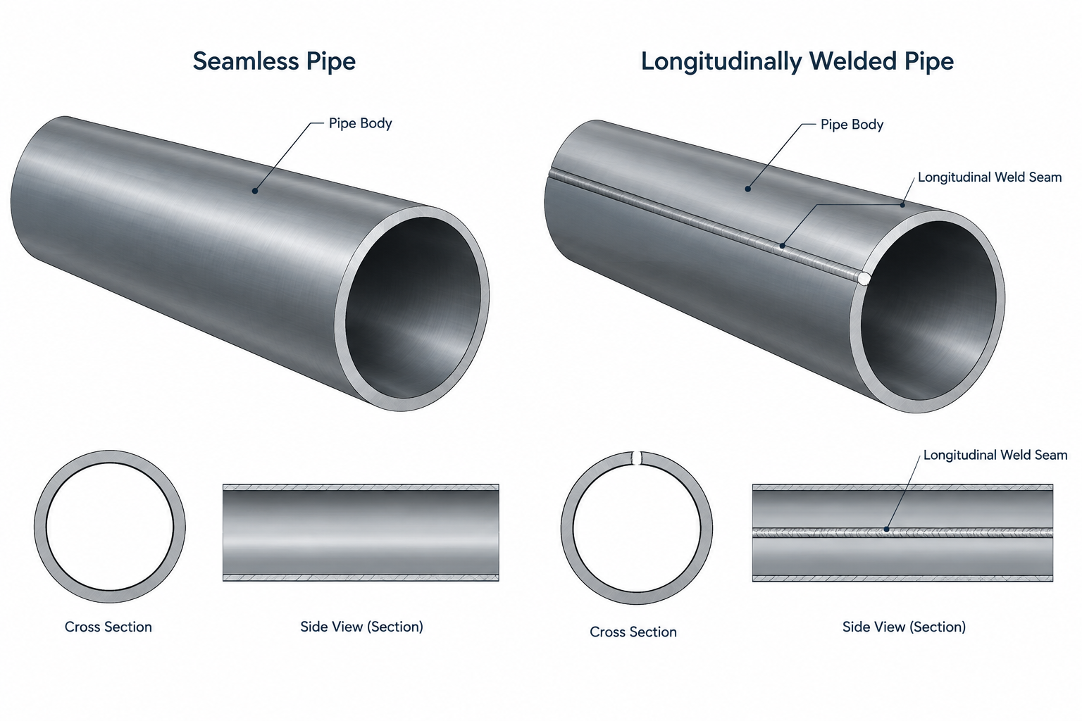
Seamless and welded pipe may use the same visible CAD geometry, yet they can represent different procurement and documentation requirements. Designers therefore need to preserve the specified product form in catalog records, piping classes, isometric outputs, and bills of material rather than relying on the appearance of the model.
This guide explains where that distinction belongs, how a manufacturing seam differs from an assembly weld, and when seam representation is relevant to a drawing. It also highlights the limits of CAD data: the model communicates design intent, while approved material identification and traceability processes confirm the supplied product.
The difference between seamless and welded pipe begins with manufacturing, but its effects extend into material specifications, procurement, inspection, fabrication, and documentation. For a CAD designer, the most important question is usually not whether to draw a visible seam. It is whether the model, isometric, bill of materials, and line data preserve the specified pipe product correctly.
Seamless and welded pipe can share the same nominal pipe size, schedule, outside diameter, and nominal wall thickness. Those dimensional labels alone do not identify the manufacturing route. A schedule table can help define geometry, but it does not replace the material and product specification used to purchase the pipe.
What Seamless Pipe Means
Seamless pipe is produced without forming a strip or plate into a cylinder and joining its edges with a longitudinal or helical weld. The manufacturing process creates a hollow pipe body that does not contain a conventional seam weld running along its length.
The word seamless describes the product form. It does not, by itself, define the alloy, grade, pressure capability, heat treatment, inspection level, or suitability for a particular service. Those requirements come from the complete piping specification and applicable project documents.
A common documentation mistake is to treat “seamless” as a general indication of quality. That is too broad. Product quality depends on the governing specification, manufacturing controls, testing, traceability, and acceptance criteria. Seamless pipe may be required for a service, but the reason must come from an engineering or procurement requirement rather than a drafting assumption.
What Welded Pipe Means
Welded pipe is made by forming flat material into a cylindrical or tubular shape and joining the edges. Depending on the product and manufacturing process, the seam may be longitudinal or helical. Different welding processes can also be used, and their abbreviated names should not be substituted casually because the accepted terminology may depend on the governing product specification.
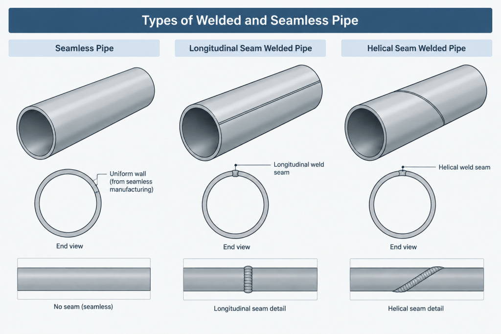
The manufacturing seam is part of the pipe product. It is different from a fabrication weld used to join one pipe length to another, attach a fitting, or connect the pipe to a flange. This distinction matters on weld maps and isometrics: a shop or field circumferential weld is normally tracked as an assembly weld, while the pipe manufacturer’s seam is controlled through the pipe product documentation.
Dimensional Labels Do Not Identify the Manufacturing Method
NPS, DN, schedule, nominal wall thickness, and outside diameter are dimensional or nominal descriptors. They do not independently answer whether a pipe is seamless or welded.
Two pipe items may appear geometrically identical in a CAD model while differing in:
- Manufacturing method
- Material grade or product specification
- Heat treatment condition
- Inspection and testing requirements
- Permitted service or temperature range
- Procurement description and material code
- Traceability documentation
This is why a generic CAD cylinder is not a complete pipe definition. Geometry supports layout, but the associated metadata determines what the object represents.
Where the Requirement Should Be Found
The pipe manufacturing route may be stated directly or encoded through a project material item. Designers should check the controlled sources used by the project rather than infer the answer from model appearance.
| Document or data source | What to check | Common risk |
|---|---|---|
| Piping material specification | Permitted product form, material specification, grade, size range, and service restrictions | Reading only the schedule and overlooking the pipe type |
| Line class or piping class | Pipe item description and linked commodity or catalog code | Using a generic pipe item across incompatible classes |
| Line list | Line class, design conditions, service, and special notes | Expecting the line list to contain every procurement detail |
| CAD or plant-design catalog | Long description, short description, material code, and class assignment | Correct geometry linked to the wrong database record |
| Bill of materials | Complete pipe description and quantity basis | Output that says only “pipe” plus size and schedule |
| Purchase documents | Product specification, grade, manufacturing route, and supplementary requirements | Adding procurement requirements that were never authorized |
| Material test documentation | Identity, heat or lot traceability, product form, and reported tests | Assuming CAD metadata proves delivered material compliance |
Should a Welded Pipe Seam Be Drawn in CAD?
In most general piping layouts and isometrics, the manufacturer’s seam is not drawn as a line along every welded pipe segment. Showing it universally can create clutter and may be mistaken for a fabrication weld, split line, or hidden edge.
A seam may need explicit representation when its orientation affects fabrication, inspection, forming, branch placement, or a project-specific detail. Examples can include specialty fabrication drawings, seam-orientation requirements, or records prepared for a defined quality-control purpose. In those cases, the drawing should use an unambiguous note or symbol defined by the project rather than an unexplained line.
Do not invent seam orientation in a model. Unless the pipe item and fabrication workflow control rotational orientation, the CAD geometry may not correspond to the seam position on the delivered pipe. A modeled seam that cannot be maintained through procurement and fabrication creates false precision.
Seam Welds vs. Fabrication Welds
Keeping weld categories separate prevents incorrect weld counts and inspection records.
- Manufacturing seam: Created when welded pipe is produced and governed by the pipe product requirements.
- Shop weld: Made by the fabricator while assembling a spool or piping component.
- Field weld: Made during installation at the site.
- Attachment weld: Used for items such as supports, lugs, or other attachments when permitted by the design.
A welded pipe length should not automatically add a seam weld to the isometric weld list. Conversely, describing the pipe as welded does not eliminate the need to identify its shop and field assembly welds.
How Manufacturing Method Affects CAD Data
The model often uses the same outside geometry for seamless and welded pipe of the same dimensional designation. The distinction should therefore be carried through properties and catalog structure.
Use separate material or commodity records
If the piping specification distinguishes seamless and welded products, the catalog should preserve that distinction. Avoid mapping both to a vague description merely because their graphical dimensions match.

Keep descriptions complete but readable
A useful pipe description generally identifies the nominal size, wall designation, material or grade reference, and required product form. The exact sequence should follow the project’s naming convention. Abbreviations should be controlled so that procurement and fabrication interpret them consistently.
Do not encode engineering rules only in graphics
Color, layer, or line type may help users review a model, but visual formatting is not a reliable substitute for properties. Plotting, file exchange, and model export can remove those visual distinctions.
Check catalog filters and size ranges
A class may permit different product forms in different size ranges or under different conditions. A broad catalog filter can expose an item that is dimensionally compatible but not allowed by the piping specification. Any range or service restriction must be taken from controlled project data.
Common Misunderstandings
- “Schedule tells me whether it is seamless.” Schedule identifies a nominal wall series, not the manufacturing method.
- “Welded pipe means every drawing needs a longitudinal weld symbol.” The manufacturing seam is normally handled as a product characteristic, not an assembly weld callout.
- “Seamless pipe is always stronger.” Performance cannot be determined from the word seamless alone. Material, dimensions, manufacturing requirements, condition, and applicable design rules all matter.
- “The same CAD geometry means the items are interchangeable.” Geometric compatibility does not establish material, service, inspection, or procurement equivalence.
- “A model property confirms the delivered pipe.” CAD data records design intent. Receiving inspection and material traceability establish what was actually supplied.
A Practical Review Workflow
- Start with the line number and confirm the assigned piping class.
- Open the controlled material specification or class record for the pipe item.
- Verify the required product form instead of inferring it from size or schedule.
- Confirm that the CAD catalog item carries the correct description and commodity code.
- Check that the bill of materials preserves the manufacturing-method distinction.
- Review any size-range, service, or special fabrication restrictions documented by engineering.
- Show seam orientation only when a controlled requirement makes it relevant.
- At material receipt or fabrication, rely on approved identification and traceability procedures rather than model appearance.
The Key Documentation Principle
For most piping CAD work, seamless and welded pipe are a data distinction before they are a graphical distinction. Their centerlines, outside envelopes, and nominal wall geometry may look identical, but the purchase descriptions and permitted applications may not be interchangeable.
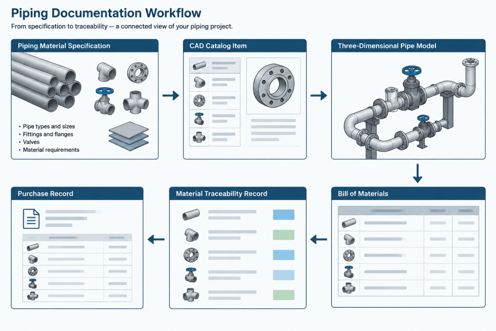
A reliable workflow keeps geometry, piping-class data, material descriptions, bills of material, and traceability roles aligned. The drawing should communicate what users need without implying that an ornamental seam line or generic model shape proves product compliance.
Documentation Checks Beyond Model Geometry
A useful CAD review should follow the pipe identity through every output that depends on the model. The object may look correct in plan, elevation, and isometric views while still carrying an incomplete description or an incorrect catalog assignment.
Check the data handoff
- Model to isometric: Confirm that the generated description retains the required product form and does not reduce the item to size and wall designation alone.
- Model to bill of materials: Verify that grouping rules do not combine seamless and welded pipe simply because their geometric properties match.
- Catalog to piping class: Confirm that the selected record is authorized by the controlled class rather than merely available in the software catalog.
- Design to procurement: Make sure the output provides the approved item identity without adding requirements that engineering has not specified.
- Procurement to receiving: Keep the boundary clear between design metadata and the documentation used to verify delivered material.
Review changes as data changes
If engineering revises the permitted pipe product, updating a note on one drawing may not be enough. The affected catalog item, class assignment, model objects, descriptions, reports, and issued documents may all require controlled review. This is especially important when geometry does not change, because an ordinary visual comparison may not reveal the revision.
Avoid ambiguous abbreviations
Short descriptions are useful in crowded outputs, but an abbreviation should have one controlled meaning across the project. If different teams interpret the same shorthand differently, the apparent efficiency can create errors during purchasing, fabrication, or material control. The full description and the project abbreviation convention should remain aligned.
Frequently Asked Questions
Can CAD geometry identify whether pipe is seamless or welded?
Not by itself. Pipe with the same dimensional designation may have the same modeled envelope regardless of manufacturing route. The distinction normally depends on the associated catalog, class, material, and commodity data.
Should the longitudinal seam of welded pipe appear on an isometric?
Not as a routine graphical feature. It should be shown only when a controlled fabrication, inspection, or orientation requirement makes it relevant. Any representation should use the project-defined note or symbol so it cannot be confused with an assembly weld.
Does pipe schedule determine whether the product is seamless or welded?
No. Schedule is a nominal wall designation. The required manufacturing route must be established by the applicable piping specification, class, material item, or other controlled project documentation.
Is a manufacturing seam included in the shop or field weld count?
It should not automatically be treated as an assembly weld. Shop and field weld tracking generally covers joints created during spool fabrication or installation, while the manufacturing seam belongs to the pipe product and its supporting documentation.
Can seamless and welded pipe share one CAD catalog record?
A project should not combine them in a way that loses an engineering or procurement distinction. Catalog structure must preserve the authorized product identity, descriptions, class rules, and output behavior required by the project.
Does correct model metadata prove that the delivered pipe complies?
No. Model metadata records design intent. Delivered material must be checked through the project’s approved receiving, identification, inspection, and traceability procedures.