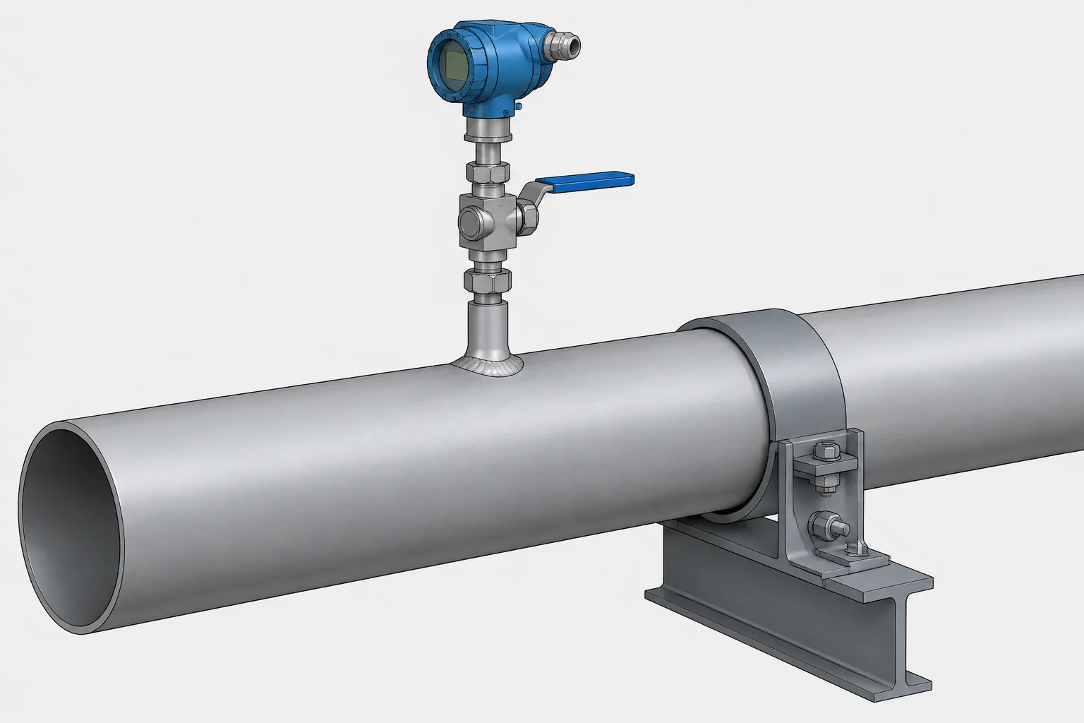
Small-bore piping connections in CAD require more attention than their compact geometry may suggest. A branch that looks acceptable in a general model view can still create problems with valve access, insulation, fabrication, support, maintenance, or vibration response.
This guide explains how to represent the complete assembly rather than treating the connection as a simple branch line. The emphasis is on practical model review, interdisciplinary coordination, and clear documentation without assuming that CAD geometry alone confirms mechanical acceptability.
Small-bore piping connections can occupy very little space in a CAD model while creating disproportionately important layout, fabrication, and reliability concerns. Typical examples include vents, drains, pressure connections, sample points, chemical injection points, bypasses, and auxiliary piping attached to a larger process line or equipment nozzle.
The term small bore is usually defined by a project, owner, or engineering practice rather than by one universal size boundary. For CAD work, the more useful distinction is functional: a small branch and its attached components may behave like a cantilever connected to a larger pipe. Its orientation, unsupported length, component mass, and exposure to vibration therefore matter as much as its nominal size.
A complete model must show more than the branch outlet. It should communicate the physical load path, operating access, fabrication arrangement, and information needed for engineering review.
What belongs to a small-bore connection assembly?
A small-bore assembly often starts at a branch outlet on a run pipe, fitting, vessel nozzle, or equipment connection. Depending on its service, the assembly may include:
- A welded outlet fitting, fabricated branch, coupling, boss, or threaded connection
- A nipple, pipe segment, or short spool
- A root valve or first isolation valve
- Additional block, bleed, check, or regulating valves
- An instrument, tubing transition, hose connection, cap, plug, or blind
- A vent, drain, sample, injection, or flushing termination
- A bracket, clamp, guide, or other support attachment
Not every assembly needs all of these items. The applicable P&ID, piping specification, instrument detail, equipment package, and project standard should establish what is required. CAD should represent those requirements without silently substituting a generic arrangement.
Why small geometry creates large layout consequences
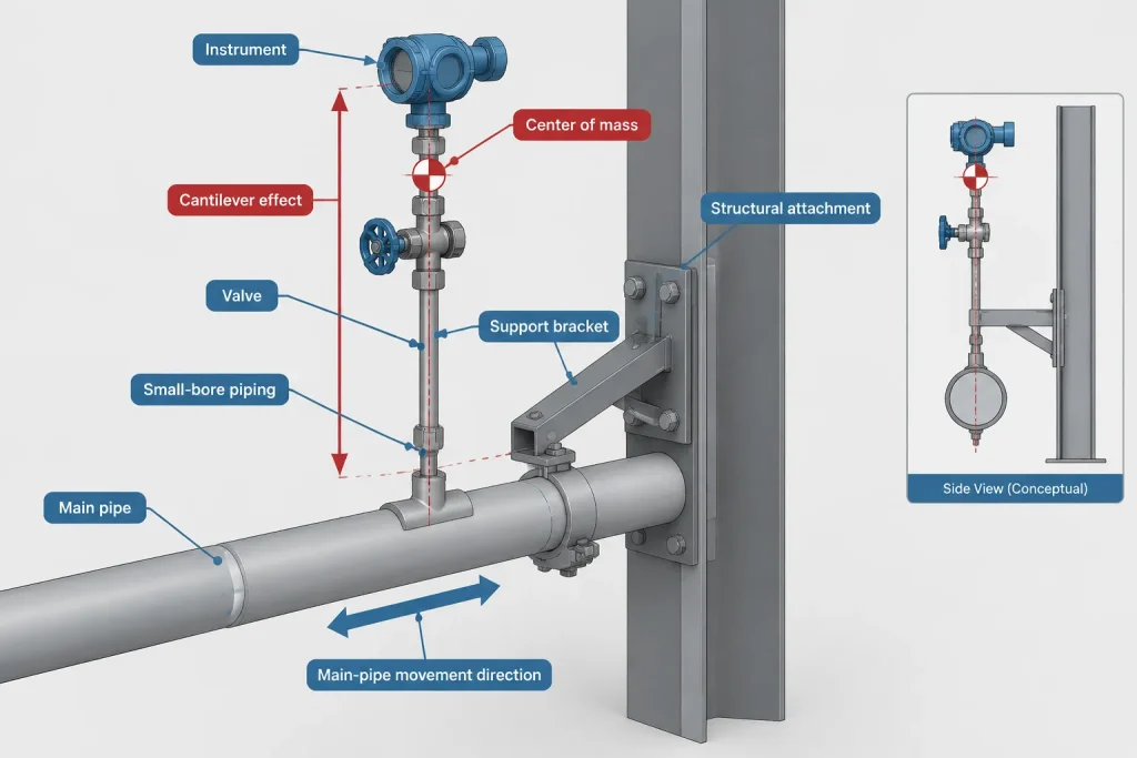
A short branch may appear rigid when viewed alone. Once valves, instruments, fittings, or operating extensions are attached, the center of mass can move significantly away from the main pipe wall. This increases leverage at the branch connection.
The CAD model does not determine whether the resulting loads are acceptable. It can, however, expose the geometry that influences the assessment. Reviewers should be able to identify the branch origin, orientation, component mass locations, support points, and relationship to potential vibration sources.
Particular attention may be appropriate near reciprocating or rotating equipment, control valves, pressure-reducing devices, flow disturbances, pulsating services, and piping known to experience movement. Proximity alone does not prove a vibration problem, but it can justify a more focused engineering review.
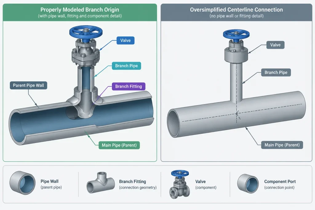
Model the connection from the actual branch origin
The branch should originate at the modeled surface or connection point of the parent component, not at an arbitrary point near its centerline. This distinction affects branch projection, cut length, clearance, and support location.
The correct origin depends on the connection type. A welded outlet fitting has different physical geometry from a coupling, a fabricated stub-in branch, or a flanged nozzle. A simplified model may omit weld profiles and minor details, but its ports and controlling dimensions should still represent the intended assembly.
Do not use linework as a substitute for a physical component
A single line extending from the main pipe can communicate schematic intent, but it does not reveal the envelope of a valve operator, instrument body, flange, or support clamp. Where congestion, access, or fabrication is being reviewed, use enough three-dimensional or double-line geometry to show the parts that control the layout.
Conversely, unnecessary cosmetic detail can make a model difficult to maintain. Threads, small fasteners, internal valve parts, and exact weld contours are rarely needed for general arrangement work. The level of detail should match the decision being made.
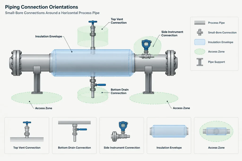
Control orientation with purpose
Branch orientation should reflect function rather than merely the clearest direction in the model view. High-point vents, low-point drains, pressure taps, sample points, and injection connections can have different process and maintenance needs.
Before fixing the orientation, check:
- Whether the process function depends on connection location around the pipe circumference
- Whether liquid or vapor can reach the connection as intended
- Whether the valve can be operated safely and conveniently
- Whether caps, plugs, instruments, or removable items can be accessed
- Whether discharge from a vent or drain is routed to an appropriate destination
- Whether the branch interferes with insulation, heat tracing, platforms, structure, or adjacent piping
- Whether the orientation creates an exposed projection vulnerable to impact
Clocking should be documented with a clear project reference. Avoid relying on ambiguous phrases such as “left side” or “rear” when a drawing view, plant direction, coordinate system, or equipment orientation provides a more stable reference.
Keep the root valve close—but verify the complete arrangement
Many small-bore assemblies place the first isolation valve near the parent pipe or equipment connection. A compact arrangement can reduce the unsupported lever arm and minimize trapped volume. It may also improve isolation by limiting the amount of branch piping between the process and the valve.
Compactness is not the only consideration. The valve body, bonnet, stem, handle, welding access, insulation, and future maintenance all require space. Placing a valve too close to the run pipe can create fabrication difficulties or prevent full operation after insulation is installed.
The appropriate arrangement must come from the governing project documents and engineering review. CAD should allow users to see the actual component envelope rather than assuming that a symbol-sized valve will fit.
Support the assembly, not just the pipe centerline
A support that appears close in plan may provide little restraint in the direction that matters. Review the three-dimensional load path from the attached component back to a sufficiently stable pipe, structure, or equipment feature.
Support planning should consider:
- Unsupported branch projection from the parent wall
- Mass and center of gravity of valves, instruments, and fittings
- Direction of expected vibration or movement
- Thermal movement of the main line relative to nearby structure
- Loads introduced during valve operation or maintenance
- Whether a bracket could unintentionally restrain required pipe movement
- Access for welding, bolting, adjustment, inspection, and removal
A brace is not automatically beneficial. Connecting a moving pipe to a fixed structure without understanding relative displacement may transfer loads into the branch or support. Support concepts should therefore be coordinated with piping stress, vibration, structural, equipment, and instrumentation disciplines as applicable.
Account for insulation and removable items
Insulation can hide the true relationship between the branch, valve, and parent line. Model or otherwise check the insulation envelope where it affects access and fit. The branch neck may need sufficient projection for the valve, flange, threads, weld, or removable cover to remain usable outside the insulation system.
Also check the removal path for instruments, plugs, caps, strainers, and valve internals. A component can fit in its installed position but still be impossible to remove because of a nearby beam, tray, handrail, or larger pipe.
Represent data as carefully as geometry
Small-bore items are easily omitted from bills of material when they are drawn as anonymous graphics. Intelligent components should carry the properties required by the project workflow, such as line identifier, nominal size, piping class, component type, connection type, service, and tag where applicable.
Maintain a clear boundary between piping, instrumentation, tubing, equipment-vendor supply, and support scope. A visible transition in the model does not by itself explain who specifies, purchases, fabricates, or installs each item.
| CAD item | Primary review question |
|---|---|
| Branch outlet | Is its type, size, location, and orientation consistent with the design documents? |
| Root valve | Can it be fabricated, operated, insulated, and maintained? |
| Instrument or accessory | Is its physical envelope and removal path represented? |
| Support or brace | Does it provide a credible load path without conflicting with pipe movement? |
| Termination | Is a vent, drain, sample, or injection destination clearly defined? |
| Component data | Will the assembly appear correctly in drawings and material reports? |
Drawing and isometric documentation
The model and drawings should agree on the connection location, orientation, component sequence, and scope boundary. Isometrics may need dimensions that establish the branch position along the main run and its direction around the pipe. Orthographic details can be more effective when support geometry, operator access, or nearby obstructions are difficult to understand on an isometric.
Do not overload a drawing with dimensions that can conflict. Control the features needed for fabrication and installation, while allowing derived geometry to remain derived. Where field orientation or final routing is intentionally adjustable, state that intent through the approved project notation rather than leaving the assembly ambiguous.
A practical CAD review sequence
- Confirm the connection against the P&ID, line data, instrument information, and piping specification.
- Verify the branch type and its physical origin on the parent component.
- Check circumferential orientation and process function.
- Review the complete assembly envelope, including operators and removable parts.
- Inspect the unsupported projection and identify significant attached mass.
- Coordinate support needs and relative movement with the responsible disciplines.
- Check insulation, heat tracing, access, discharge routing, and nearby obstructions.
- Verify component properties, scope boundaries, drawing output, and material reporting.
Small-bore piping connections should not be treated as minor decorations added after the main routing is complete. Modeling them early enough for coordination helps reveal access conflicts, weak support concepts, ambiguous scope, and vibration-sensitive arrangements before they reach fabrication or the field.
Turn model observations into coordinated design decisions
A useful CAD review should distinguish between a visible condition and an engineering conclusion. For example, a long projection, concentrated component mass, or nearby vibration source can be identified in the model. Whether that arrangement is acceptable must be determined by the responsible engineering disciplines using the applicable project requirements.
When a concern is found, record enough context for another reviewer to understand it. The issue should identify the affected connection, the observed geometry, the operating or maintenance concern, and the discipline expected to resolve it. A vague note such as check support is less useful than a comment explaining that the valve and instrument assembly projects away from the parent line and lacks a clearly modeled restraint path.
Manage model maturity and unresolved details
Small-bore assemblies often develop through information supplied by piping, instrumentation, equipment vendors, structural designers, and operations personnel. During early design, some component envelopes or support details may remain provisional. These uncertainties should be visible in the project workflow rather than hidden behind generic CAD graphics.
- Use placeholders deliberately: Mark conceptual components so they are not mistaken for approved catalog items.
- Track scope interfaces: Identify where piping ends and tubing, vendor supply, instrumentation, or support scope begins.
- Protect controlling references: Maintain the intended branch origin, orientation, and connection sequence as component details are refined.
- Repeat clash reviews: Recheck insulation, operators, removal paths, and supports after adjacent systems change.
- Close review comments visibly: Confirm that an accepted resolution appears in the model, drawings, and associated data.
Check consistency across deliverables
The model, isometric, support detail, material output, and instrument documentation should describe the same physical arrangement. A connection is not fully coordinated if its geometry appears in the model but its components are missing from reports, or if a drawing shows an orientation that differs from the coordinated model.
Final review should also consider constructability. Confirm that welds, threaded joints, bolted connections, clamps, and removable components remain reachable in the expected installation sequence. If field adjustment is permitted, the documentation should make that flexibility explicit and preserve the functional and access requirements that cannot change.
Frequently asked questions
What is considered small-bore piping?
There is no single universal boundary for every project. The governing owner, project, or engineering practice should define the term. For CAD review, the important issue is often whether a compact branch with attached components creates a cantilevered, access-sensitive, or vibration-sensitive assembly.
Why should the branch origin be modeled accurately?
The physical origin affects projection, cut length, clearance, support placement, and the relationship between the outlet and parent component. Starting a branch at an arbitrary centerline point can conceal fabrication and fit-up problems.
Does a nearby support make a small-bore connection acceptable?
Not necessarily. The support must provide a credible load path in the relevant direction while accommodating required movement of the main piping. Its suitability requires engineering review rather than a visual distance check alone.
Should valve operators and instruments be modeled in detail?
Model enough of their external envelope to evaluate access, clashes, center-of-mass effects, and removal. Internal parts and cosmetic manufacturing detail are generally unnecessary unless they support a specific project decision.
How should vibration risk be handled in CAD?
CAD can reveal geometry associated with potential concern, including unsupported projection, attached mass, orientation, and proximity to possible excitation sources. It cannot establish vibration acceptability by itself. Flag the arrangement for review by the appropriate engineering disciplines.
What should be checked when insulation is present?
Check the insulation envelope, branch projection, valve operation, joint access, support interaction, and removal path for instruments, caps, plugs, and other serviceable items. Installed fit alone does not confirm maintainability.