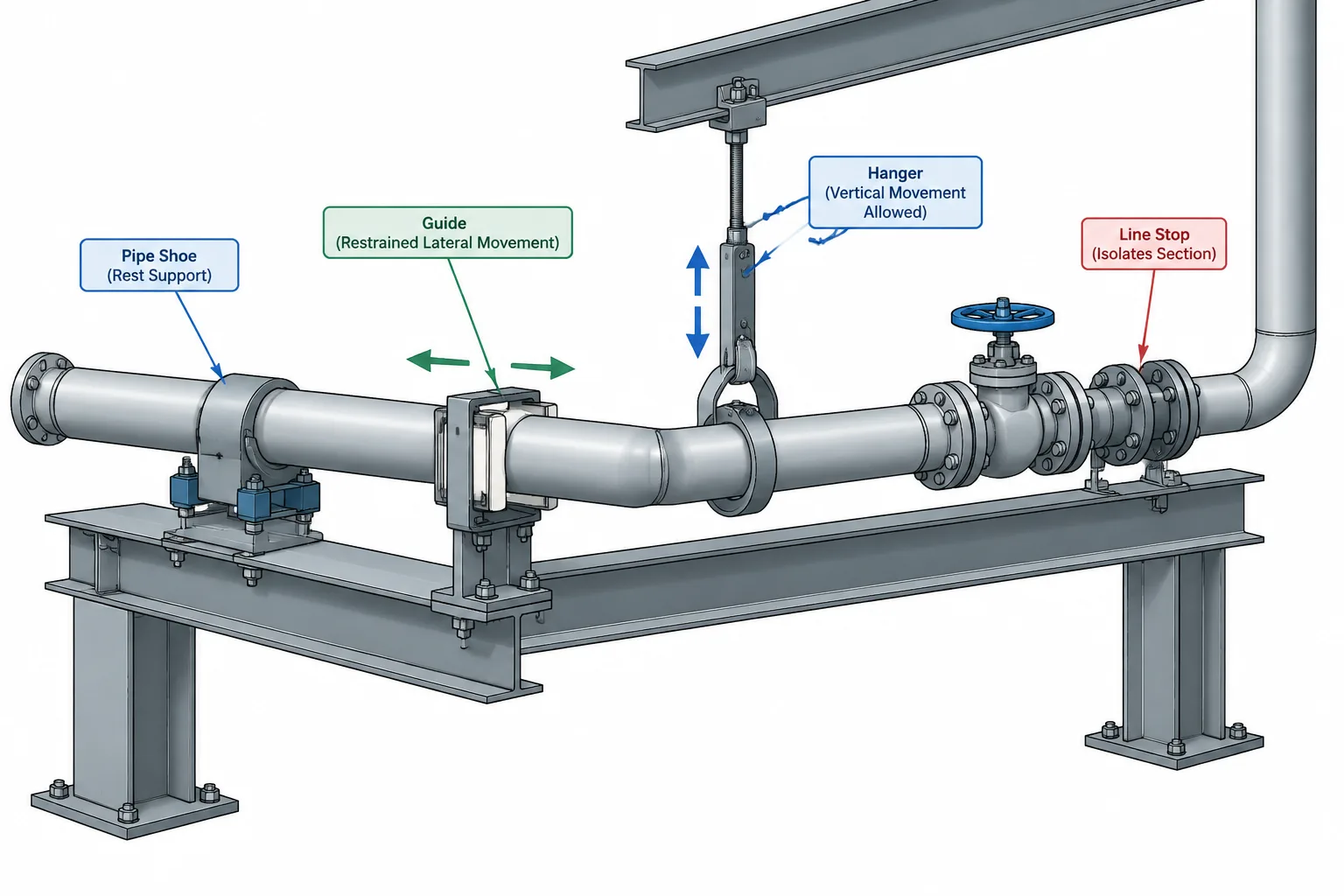
Piping support locations in CAD must represent more than convenient points beneath a pipe route. Each location is part of a load path and movement-control strategy that must align with the available structure, piping behavior, installation needs, and project documentation.
This guide explains how designers can develop and coordinate support locations without confusing preliminary model placement with final engineering approval. It focuses on support function, span influences, concentrated loads, thermal movement, access, structural interfaces, and reliable multidisciplinary handoffs.
Piping support locations in CAD are not simply points placed at regular intervals along a route. Each location must connect the piping system to a structure while controlling weight, movement, vibration, and alignment without creating an unintended restraint. A support that looks reasonable in a model may be ineffective, inaccessible, structurally impractical, or harmful to system flexibility.
The piping designer normally develops support concepts in coordination with stress analysis, structural design, equipment requirements, and the project piping specification. CAD geometry helps organize this work, but geometry alone cannot determine whether a support is adequate. The design team must also understand what the support is expected to do.
What a piping support location represents
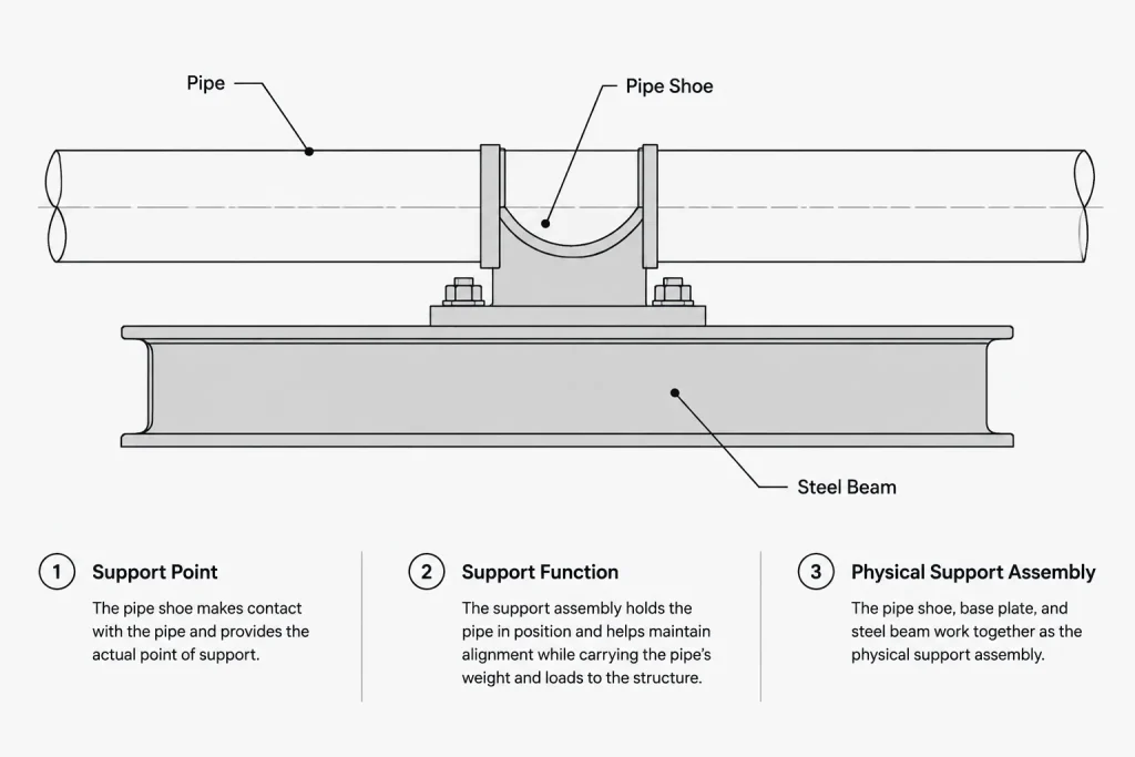
A support location identifies where load or restraint is transferred between the pipe and another object. That object may be structural steel, concrete, a pipe rack, an equipment support frame, or a dedicated support assembly.
Three related items should be kept distinct:
- Support point: The station or coordinate where the pipe is supported or restrained.
- Support function: The intended behavior, such as vertical support, lateral restraint, directional guidance, anchoring, or spring support.
- Support assembly: The physical combination of pipe attachment, load-bearing element, steelwork, fasteners, and connection to the supporting structure.
A CAD symbol may identify the support point without fully defining the assembly. Conversely, a detailed support model does not prove that its function or load capacity is correct. Drawings and model data should make the distinction clear.
Why equal spacing is only a starting concept
Allowable pipe span is influenced by pipe size, wall, material, operating condition, contents, insulation, concentrated loads, deflection limits, and the project design basis. These factors are not visible from a centerline route alone. A generic span guide may assist preliminary layout, but it should not replace project criteria or engineering review.
Support spacing often changes near fittings and components. Valves, strainers, flanges, specialty items, inline instruments, and branch assemblies can introduce loads that differ significantly from those of straight pipe. A long run that appears uniformly loaded in CAD may actually require locally closer support or a different support function.
Concentrated component loads
Heavy inline components should be considered individually rather than treated as ordinary pipe. The designer should evaluate how the component is supported during normal operation, maintenance, and disassembly. Placing one support on each side may appear conservative, but the resulting arrangement can restrict thermal movement or make bolted joints difficult to access.
Changes in direction
Elbows and offsets redirect pipe movement and force. Supports near a change in direction may serve as guides or restraints rather than simple weight supports. Their exact location can affect both system flexibility and the loads transferred into nearby steel.
Vertical runs
Vertical piping requires a different support concept from horizontal piping. The design may need to carry vertical dead weight, limit lateral motion, accommodate thermal growth, and avoid placing excessive load on equipment nozzles or branch connections. A support symbol shown beside a riser should therefore identify its function and attachment elevation clearly.
Support functions that CAD users should distinguish
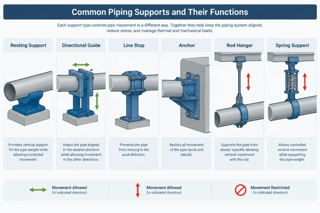
| Support function | Primary purpose | CAD and coordination concern |
|---|---|---|
| Resting support | Carries vertical weight while potentially allowing sliding | Confirm bearing elevation, contact surface, and sliding direction |
| Guide | Limits transverse movement while permitting movement along an intended axis | Show guide direction and check that surrounding steel does not create an unintended anchor |
| Line stop | Restrains movement along the pipe axis in a selected direction or directions | Document restraint direction and coordinate the resulting structural load |
| Anchor | Restrains defined translations and, where intended, rotations | Do not infer anchor behavior from a rigid-looking model; identify the engineering function explicitly |
| Hanger | Supports pipe from overhead structure | Check rod alignment, attachment point, available headroom, and installation access |
| Spring support | Carries load while accommodating vertical movement | Reserve the required envelope and preserve the specified installation orientation |
These terms describe behavior, not merely appearance. For example, a pipe shoe resting on steel may slide freely, be guided, or be stopped depending on the clips, stops, clearances, and friction assumptions. The support tag and associated documentation should communicate the intended function.
Factors that should influence support placement
Operating, test, and occasional conditions
A support system may experience different load patterns when the line is empty, operating, undergoing a pressure test, or exposed to an occasional design event. A line that normally carries gas may become much heavier when filled with test liquid. Temporary supports may be required, but they should be identified as temporary rather than left to interpretation in the field.
Thermal movement
Supports must work with the expected direction and magnitude of pipe movement. Long sliding surfaces, guide gaps, shoe lengths, hanger rod swing, and nearby obstructions may all matter. CAD coordination should check both the modeled position and the movement envelope supplied by the responsible engineering discipline.
Drainage and slope
Support elevations affect pipe slope and low-point formation. Copying one support elevation across a sloped line can flatten or reverse the intended grade. The designer should coordinate centerline or bottom-of-pipe elevations with shoe heights, structural elevations, and local component geometry.
Branch connections
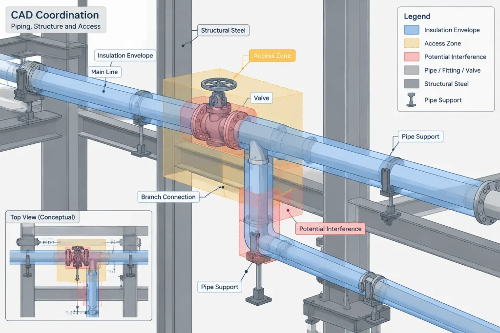
A support placed too close to a branch may interfere with welding, examination, reinforcement, insulation, or branch movement. A support placed too far away may allow the branch assembly to impose undesirable loads on the run. Branch geometry should be reviewed as an assembly rather than as an isolated centerline junction.
Maintenance and access
Supports can block flange bolts, valve operators, drain connections, instrument access, insulation removal, and component extraction. Hangers and support steel may also obstruct platforms or walkways. The model review should include access to the support itself because clamps, fasteners, and sliding surfaces may require installation or inspection.
A practical CAD workflow
- Establish the design basis. Confirm line service, material class, insulation, operating condition, test condition, slope requirements, and any available stress criteria.
- Route the pipe and identify critical zones. Mark equipment nozzles, valves, inline specialties, branches, direction changes, vertical runs, and structural crossings.
- Place preliminary weight supports. Use project guidance for initial spacing, but adjust locations for concentrated loads and available structure.
- Assign intended functions. Identify which points rest, guide, stop, anchor, hang, or use a flexible support. Avoid relying on visual appearance alone.
- Coordinate with structure. Confirm that beams, columns, concrete, or secondary steel are available where required. A floating support symbol in a piping model is not a complete design.
- Review movement and loads. Incorporate stress-analysis requirements and verify that support steel, clearances, and attachments match the intended restraint behavior.
- Check constructability. Review welding access, bolting, insulation, field adjustment, installation sequence, and maintenance access.
- Control revisions. Track changes to support location, type, tag, elevation, and function. A small routing change can invalidate a previously coordinated support.
What to document
The required information depends on project deliverables, but a coordinated support record commonly needs more than a symbol and tag. Useful fields include:
- Unique support identifier
- Associated line or spool reference
- Coordinate or station along the route
- Pipe centerline, bottom-of-pipe, or bearing elevation
- Support function and restraint directions
- Pipe attachment or shoe reference
- Supporting structure reference
- Insulation or wear-pad interface requirements
- Status, responsibility, and revision information
- Engineering loads or movement data when issued for structural design
Support details, schedules, isometrics, plans, structural drawings, and analysis data should use consistent identifiers. If different disciplines assign separate numbers, the relationship between them should be traceable.
Common CAD coordination errors
- Placing supports at visually regular intervals without considering component weight or project span criteria
- Modeling a support as rigid when it is intended to slide
- Adding guides on both sides of an elbow without checking thermal behavior
- Supporting pipe from steel that has not been confirmed or assigned to the structural scope
- Ignoring insulation, shoe height, or the gap between the pipe and supporting steel
- Copying support elevations from a level line onto a sloped line
- Leaving support tags unchanged after moving or deleting the associated geometry
- Using a generic support detail where a component, branch, or movement condition requires a project-specific solution
Final review principle
A good piping support model answers four questions: what load is carried, what movement is allowed, what movement is restrained, and where the reaction goes. If any answer is unclear, the support is not fully coordinated.
CAD should provide accurate locations, envelopes, interfaces, and identifiers. Final span limits, restraint definitions, loads, attachment design, and structural adequacy must come from the applicable project criteria and responsible engineering disciplines. Treating support locations as functional interfaces rather than decorative model objects produces clearer drawings, more reliable analysis handoffs, and fewer field changes.
Using support data through the design process
Support information often develops in stages. Early model locations may indicate where support is likely to be needed, while later updates define restraint direction, movement allowance, structural reactions, attachment details, and fabrication responsibility. The model and drawings should communicate the maturity of that information so preliminary concepts are not mistaken for approved support designs.
Separate clash clearance from movement clearance
A support may pass a static clash check and still interfere with the operating pipe position. Reviews should distinguish ordinary geometric clearance from the envelope needed for sliding shoes, moving hangers, insulation, guide gaps, maintenance activity, and field adjustment. Movement information should come from the responsible engineering discipline rather than being estimated from model appearance.
Check the complete load path
A coordinated support should be traceable from the pipe attachment through the support member and into confirmed structure. This review includes the bearing or restraint interface, secondary steel, structural connection, and receiving beam, column, concrete element, or equipment frame. If any part of that path is undefined, the support remains an interface requiring resolution.
Use model status deliberately
- Concept location: Indicates a probable support zone but does not establish final function or structural adequacy.
- Coordinated location: Aligns with the route, nearby equipment, access requirements, and available supporting structure.
- Engineering-defined support: Includes the required function, restraint direction, movement information, and issued load data where applicable.
- Detailed support: Connects the engineering requirement to an approved attachment or assembly and its supporting structure.
Project terminology may differ, but a visible status system helps prevent incomplete data from moving into fabrication or construction deliverables.
Model-review questions for support coordination
- Does the support carry the intended load under the relevant project conditions?
- Is the permitted pipe movement clear from the support function and surrounding geometry?
- Could nearby steel, clips, clamps, or insulation create an unintended restraint?
- Is the supporting structure confirmed rather than assumed from background geometry?
- Can the support and adjacent piping be installed, insulated, inspected, and maintained?
- Do the model, support schedule, isometric, detail, and structural reference use traceable identifiers?
- Have route, elevation, component, or analysis revisions affected the support concept?
These questions do not replace stress, structural, or attachment design. They help CAD users identify incomplete interfaces before those gaps become drawing conflicts or field changes.
Frequently asked questions
Can piping supports be placed at equal intervals in CAD?
Equal spacing may assist preliminary layout, but final placement depends on project span criteria, pipe condition, contents, insulation, components, branches, movement, slope, and available structure. Regular visual spacing is not evidence that the support arrangement is adequate.
What is the difference between a support point and a support assembly?
The support point identifies where the pipe transfers load or restraint. The support assembly is the physical combination of attachment, bearing or restraint elements, steelwork, fasteners, and structural connection used to perform that function.
Does a clash-free support model prove that the design works?
No. Clash detection evaluates modeled geometry in defined positions. It does not establish allowable span, load capacity, restraint behavior, thermal flexibility, attachment strength, or structural adequacy.
Who determines whether a support is a guide, stop, anchor, or spring support?
The function should be established through the project design basis and coordination among piping, stress, structural, equipment, and other responsible disciplines. CAD users should model and document the issued requirement rather than infer behavior from the support’s appearance.
Why must support movement envelopes be modeled or documented?
A pipe shoe, hanger, guide, or connected steel element may occupy different space as the piping moves. The envelope helps identify interference with structure, insulation, nearby piping, platforms, and maintenance areas.
Should temporary supports appear in project documentation?
When temporary support is required for testing, erection, transport, or another defined condition, it should be clearly distinguished from the permanent support system. Responsibility, installation status, and removal requirements should follow project procedures.