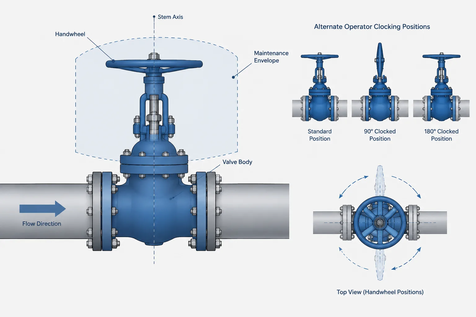
Valve stem orientation in piping CAD is a layout and documentation decision, not merely a component rotation. The valve body, stem, operator, moving envelope, maintenance space, flow direction, and service restrictions must be evaluated as related but distinct controls.
This guide explains how to coordinate those controls without treating a clear-looking model as proof that an installation position is acceptable. Product documentation, project requirements, operating access, and maintenance needs remain essential to the final decision.
A valve can fit between its piping connections and still be installed in the wrong orientation. The body may align with the line, yet the stem, handwheel, lever, gearbox, or actuator may conflict with steel, block a walkway, collect process material, or become inaccessible for operation and maintenance.
Valve stem orientation in piping CAD therefore requires more than rotating a generic component until the model looks clear. Designers must distinguish flow orientation from operator orientation, understand which installation positions are permitted, and preserve the selected orientation in drawings and model data.
Flow direction and stem orientation are different controls
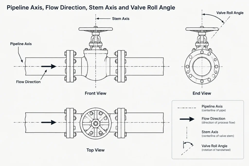
Several independent directions can apply to one valve:
- Pipeline axis: The direction of the pipe centerline through the valve connections.
- Flow direction: The intended process flow through the valve. Some valve designs are directional, while others may be used in either flow direction subject to the selected product and service.
- Stem axis: The centerline along which the stem moves or rotates.
- Operator orientation: The physical position of a handwheel, lever, gearbox, pneumatic actuator, electric actuator, or hydraulic operator.
- Local vertical direction: The relationship of the valve internals and bonnet to gravity.
Rotating a valve around the pipe centerline may leave its end connections and flow arrow unchanged while moving the operator to a completely different location. This roll angle is often the critical layout variable.
A P&ID normally communicates valve function, identification, and process relationships. Its symbol orientation should not automatically be interpreted as the required physical stem direction. The installation position belongs in the coordinated layout, component data, valve schedule, vendor documentation, or project notes as appropriate.
Why installation orientation matters
Operation and visibility
An operator must be reachable from the intended operating location. A handwheel positioned against a wall may be visible in plan but unusable in the field. A lever needs an unobstructed sweep, and a gearbox may place its input shaft on a side that cannot be reached from a platform.
Visibility also matters. Operators may need to see a position indicator, local control station, nameplate, or travel scale while standing in a safe working position. Access should be reviewed from the operator’s location rather than judged only by the absence of a hard model clash.
Maintenance and removal
The operating envelope is not the same as the maintenance envelope. A valve may operate normally while leaving no room to remove its actuator, bonnet, stem assembly, cover, or internal parts. Lifting access and the likely removal direction should be considered for heavy or awkward assemblies.
Maintenance needs vary substantially by valve construction. The selected manufacturer’s dimensional drawing and maintenance instructions should control the required clearance. A generic CAD envelope is useful for early coordination but should not be treated as verified removal space.
Process behavior and drainage
Orientation can influence whether gas, liquid, solids, or condensate collects in a valve body or bonnet region. This concern is service-specific and cannot be resolved by a universal rule such as always placing every stem vertically upward.
For example, a cavity-containing valve may require review for trapped fluid, while a valve in slurry service may need an orientation that reduces settlement in vulnerable areas. Cryogenic, sanitary, steam, vacuum, and hazardous services can introduce additional considerations. The piping specification, process requirements, and manufacturer guidance should be checked before fixing the position.
Loads on operators and stems
Large gearboxes and actuators add weight and eccentric loading. An orientation that looks convenient may create an unfavorable cantilevered condition or require external support. Actuator support, vibration, piping movement, and thermal displacement should be reviewed without unintentionally restraining the valve or pipe.
Do not assume that a valve body or actuator bracket may be rotated into any position. Product construction, mounting interfaces, lubrication, controls, drainage, and manufacturer limitations can restrict acceptable orientations.
Orientation considerations by operator type
| Operator type | Primary CAD checks | Common documentation concern |
|---|---|---|
| Handwheel | Reach, turning clearance, visibility, and interference with adjacent piping | Stem axis and operating side may need to be shown |
| Lever | Full sweep, grip access, open and closed positions, and lockout space | A static model may not communicate the complete movement envelope |
| Gear operator | Gearbox body, input shaft position, handwheel access, and support needs | Gearbox clocking should match the selected assembly |
| Pneumatic or hydraulic actuator | Actuator envelope, tubing routes, accessories, removal direction, and local controls | Fail action and physical orientation are separate properties |
| Electric actuator | Motor and housing envelope, cable entry, local control access, and removal space | Vendor geometry may be required before the orientation is finalized |
The table is a coordination guide, not a substitute for product instructions. Two valves with similar body geometry can have very different operator restrictions.
Valve-type issues that affect orientation
Gate and globe valves
Gate and globe valves commonly have a prominent bonnet and stem assembly, making access and removal clearance easy to overlook. For a rising-stem design, the model must represent or reserve the stem’s extended position. Modeling only the closed envelope can create a false clearance condition.
Globe-pattern bodies may also be directional. Body casting marks, project data, and product documentation should be used to confirm flow direction rather than relying solely on a generic CAD symbol.
Ball and plug valves
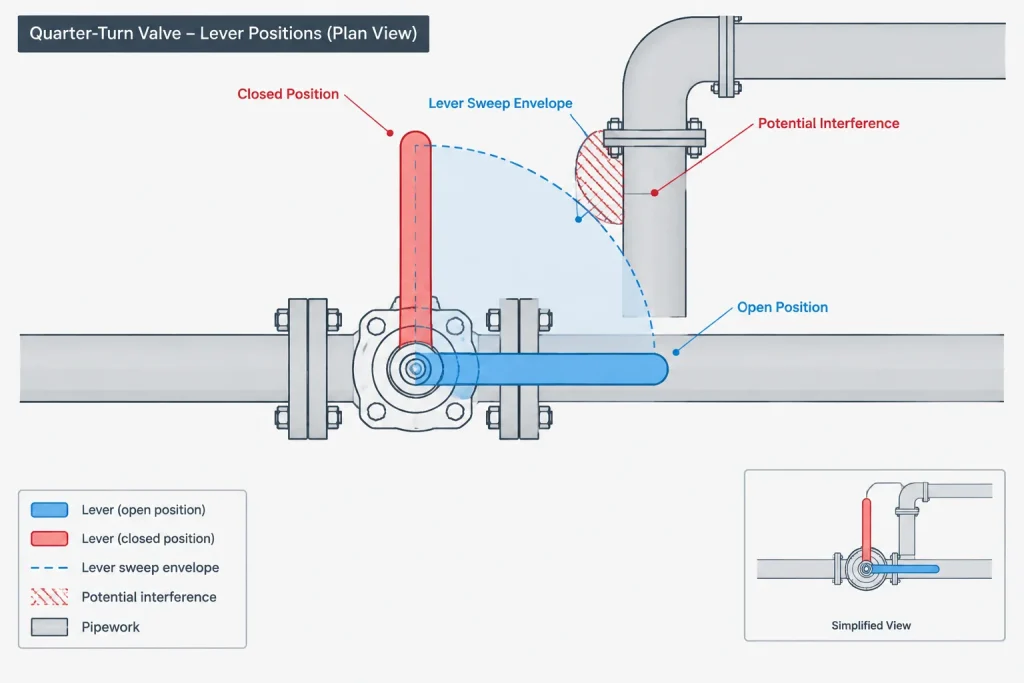
Quarter-turn valves often appear compact, but levers and actuators can occupy much more space than the body. Lever sweep should be checked in both operating positions. If the handle is removable or can be reindexed, that possibility should be verified rather than assumed.
Body cavity behavior, stem arrangement, seat design, and service conditions may affect permitted installation positions. These details are not reliably inferred from a simplified model.
Butterfly valves
A butterfly valve requires coordination of the stem and operator as well as internal disc clearance. Adjacent pipe, liners, gaskets, or nearby components can affect the disc’s ability to move. The selected valve and adjoining connection details must be reviewed together.
Check valves
Check valves deserve separate attention because orientation can directly affect internal movement. Swing, lift, dual-plate, tilting-disc, and other mechanisms do not share one universal installation rule. Gravity, flow direction, velocity behavior, and internal construction can all matter.

A generic check-valve body in a model should not be rotated merely to clear nearby objects. Confirm the allowable pipe direction and body orientation for the actual valve design.
A practical CAD orientation workflow
- Confirm the valve function and type. Start with the P&ID, line data, valve list, and piping specification. Identify whether the valve is directional and whether it is manual or actuated.
- Establish the pipe and flow axes. Connect the correct valve ports and verify any required flow direction before adjusting the roll angle.
- Use an appropriate geometry envelope. Include the body, bonnet, stem, handwheel, lever, gearbox, actuator, and significant accessories. Clearly distinguish preliminary geometry from vendor-confirmed geometry.
- Set an initial operating orientation. Position the operator toward the intended access area while avoiding walkways, escape paths, equipment access zones, and nearby components.
- Check moving geometry. Review lever sweep, rising-stem travel, indicator movement, and any other operating motion. Do not rely only on the valve’s static position.
- Check maintenance geometry. Reserve space for removal of the actuator, bonnet, cover, internals, fasteners, and attached accessories where required.
- Review service restrictions. Confirm drainage, cavity, solids, temperature, lubrication, and gravity-sensitive requirements with the responsible engineering discipline and manufacturer information.
- Evaluate loads and support. Determine whether a heavy or offset operator requires structural coordination or a purpose-designed support arrangement.
- Record the accepted orientation. Preserve the roll angle and operator direction in the model and communicate it on relevant drawings, schedules, or installation details.
How to document orientation clearly
Orientation should be communicated with the least ambiguous control suitable for the project. Possible methods include a plan or section view, an operator-side note, a stem centerline, a local coordinate direction, an angular clocking reference, or a vendor drawing reference.
Words such as left, right, front, and back are risky unless the viewing direction is defined. Compass directions, plant coordinates, equipment references, or clearly identified drawing views are usually easier to verify. For skewed or sloped piping, a simple plan-view note may be insufficient because the operator’s true three-dimensional direction may not be obvious.
If the orientation is not yet confirmed, label it as preliminary instead of presenting it as fabrication-ready information. When vendor data arrives, compare connection locations, overall envelope, stem axis, operator clocking, accessory positions, and maintenance clearances against the placeholder model.
Common orientation mistakes
- Reading physical valve orientation directly from the P&ID symbol.
- Checking the valve body but omitting the operator envelope.
- Modeling a lever in one position without checking its full sweep.
- Ignoring the extended height of a rising stem.
- Rotating a gravity-sensitive check valve to solve a clash.
- Assuming an actuator can be mounted in any clock position.
- Providing operating access but no maintenance removal space.
- Leaving the final orientation only in the model without communicating it to fabrication or installation teams.
- Replacing a valve with another model while losing the approved operator clocking.
Final review principle
A correctly oriented valve satisfies several conditions at once: its ports and flow direction are correct, its internal mechanism is installed in an acceptable position, its operator is accessible, its moving parts are clear, and its maintenance envelope is coordinated. The chosen orientation must also be visible in the project documentation.
CAD can reveal clashes and preserve clocking, but it cannot determine every permitted installation position from geometry alone. Final orientation should combine model coordination with piping requirements, process considerations, operating access, maintenance planning, and verified product information.
Use orientation status as a design control
A useful model should communicate whether valve orientation is conceptual, coordinated, or confirmed from selected-product information. This distinction helps prevent preliminary operator geometry from being treated as approved fabrication information.
- Conceptual: The component represents the intended valve type and approximate operator arrangement for early layout work.
- Coordinated: Access, movement, surrounding structures, piping, and maintenance needs have been reviewed using the available information.
- Product-confirmed: The modeled arrangement has been compared with applicable manufacturer information and project requirements.
The terminology used for these states should follow the project execution plan. What matters is that model users can identify the reliability of the displayed orientation.
Separate clash clearance from functional clearance
A hard-clash check only shows whether modeled objects overlap. It does not prove that a person can operate the valve, that a lever can complete its travel, or that maintenance personnel can remove the operator or internal assembly.
Design reviews are more effective when clearance is considered in separate categories:
- Static envelope: The space occupied by the installed body, bonnet, stem, operator, and accessories.
- Operating envelope: The space needed for hand movement, lever travel, stem movement, indicators, and local controls.
- Maintenance envelope: The access and removal path required for serviceable components, tools, lifting, and handling.
- Human access: The working position from which an operator or maintainer can see, reach, and use the equipment.
These envelopes may overlap, but they should not be assumed to be interchangeable.
Protect orientation during model changes
Valve replacement is a common point of failure in model coordination. A substituted component may retain the correct connection points while resetting its roll angle, reversing an operator side, or changing the actuator envelope. Replacement checks should therefore include more than port alignment.
- Compare stem and operator direction with the accepted arrangement.
- Recheck moving and maintenance envelopes.
- Verify flow direction and connection mapping.
- Review accessories, cable entries, tubing routes, indicators, and local controls.
- Confirm that drawings and schedules still describe the model correctly.
A clearly recorded orientation requirement makes these checks easier during design revisions, vendor-model updates, and fabrication handoff.
Frequently asked questions
Is the orientation of a valve symbol on a P&ID an installation instruction?
Not by itself. A P&ID primarily communicates process function and relationships. Physical stem and operator orientation should be established through coordinated layout information, project documentation, and applicable product requirements.
Can a valve be rotated around the pipe centerline to clear a clash?
Only after confirming that the revised position is permitted for the selected valve, operator, and service. A clash-free rotation can still create operating, drainage, loading, internal-mechanism, or maintenance problems.
What should be included in a valve operator envelope?
The envelope should represent the relevant operator body and accessories as well as operating movement and removal needs. The required detail depends on the valve type, project phase, and reliability of the available product information.
Why is a lever valve not adequately represented by one static handle position?
A static position does not show the complete sweep between operating positions. The movement can conflict with adjacent piping, structural members, insulation, equipment, or access areas even when the displayed handle is clear.
How should an unconfirmed valve orientation be shown?
Identify it as preliminary and avoid presenting it as fabrication-ready. The project should also define where the final orientation is controlled, such as the model, an arrangement drawing, a schedule, an installation detail, or selected-product documentation.
Who should review valve orientation?
Review responsibilities depend on the project, but layout, piping, process, operations, maintenance, structural, instrumentation, and supplier information may all affect the decision. The model should support coordination rather than replace discipline review.