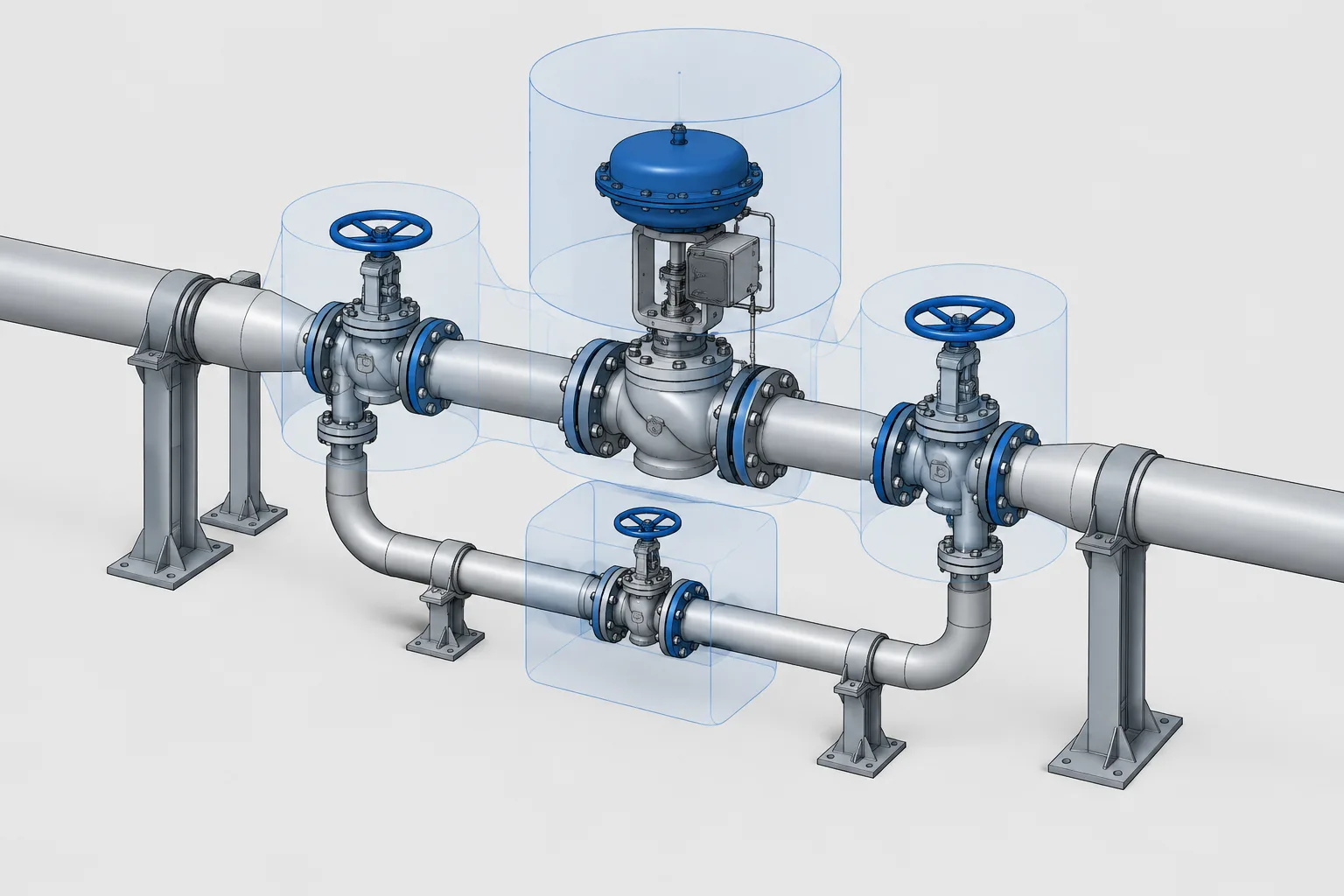
A reliable control valve station layout must translate process intent into piping that can be constructed, operated, isolated, inspected, and maintained. The CAD arrangement should account for the complete assembly rather than treating the control valve as a standalone component.
This guide explains how bypass routing, isolation boundaries, actuator clearance, break joints, support locations, drains, vents, and removal paths interact. Final geometry should always be checked against approved project documents, vendor information, operating requirements, and discipline-specific reviews.
A control valve station is more than a control valve inserted into a pipe run. It may include isolation valves, a bypass, reducers, drains, vents, instruments, supports, and enough open space to operate and remove the equipment. The P&ID establishes the station’s functional arrangement, but the piping designer must convert that arrangement into buildable and maintainable geometry.
There is no universal control valve station layout. The correct arrangement depends on the process function, valve type, line specification, flow direction, operating philosophy, maintenance plan, vendor requirements, and available space. A CAD model should therefore represent verified project information rather than a generic station copied from another service.
What Is Included in a Control Valve Station?
The term generally describes a group of piping components arranged around a valve that modulates flow, pressure, level, temperature, or another process variable. Depending on the design, the station may contain:
- The control valve and its actuator or operator
- Upstream and downstream isolation valves
- A manual bypass line and bypass valve
- Reducers or expanders where the control valve connection size differs from the line size
- Drain, vent, bleed, or depressurization connections
- Pressure taps, transmitters, positioners, solenoids, or other instrumentation
- Temporary or permanent strainers where specified
- Pipe supports, guides, and structural steel
- Flanged or other removable joints needed for maintenance
Not every station uses every item. In particular, a bypass should not be assumed merely because it appears in a typical detail. Its presence, valve type, and operating purpose should be confirmed on the P&ID and in the project operating philosophy.
Start with Function Before Arranging Geometry
A compact arrangement is not necessarily a good arrangement. Before routing the station, identify what each branch and component is intended to do. An isolation valve must be operable. A drain needs a safe destination. An actuator needs room to move or be removed. A bypass intended for manual process control may need better operator access than a line used only during maintenance.
Review the following information before developing detailed geometry:
- P&ID component sequence, line numbers, and flow direction
- Piping material class and specification breaks
- Control valve data sheet and vendor dimensional information
- Valve fail action and normal operating position
- Required flow orientation through the valve body
- Instrument hook-up requirements and tubing interfaces
- Insulation, tracing, noise treatment, or personnel protection
- Operating platforms, access ways, and maintenance zones
- Drainage, venting, flushing, and testing requirements
The P&ID is authoritative for process intent, but it normally does not define physical spacing, elevation, valve orientation, or extraction paths. Those decisions must be coordinated in the layout.
Main-Line Isolation and Bypass Arrangement
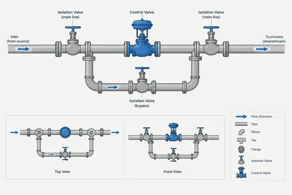
A common station concept places isolation valves upstream and downstream of the control valve, with a smaller or parallel bypass connecting around the controlled section. This arrangement can allow selected maintenance or operating activities, but its exact use is project-specific.
The bypass should be routed so that it is clearly connected to the intended pressure zones. Connecting it on the wrong side of an isolation valve can defeat the intended isolation boundary. Designers should trace the complete flow path in the model and compare it with the P&ID rather than judging the arrangement from appearance alone.
A bypass valve may require frequent manual adjustment, occasional operation, locking, sealing, or controlled access. Its handwheel, lever, gearbox, or actuator must be reachable without forcing the operator to stand on piping, insulation, or nearby equipment. If the valve is elevated, the design may require a platform, extension stem, chain operator, or another approved access solution.
Control Valve Size and Reducer Placement
A control valve may have smaller end connections than the adjoining process line. This does not automatically mean the pipe run should be modeled at the valve size for an arbitrary distance. The transition arrangement should follow the approved valve selection, piping specification, hydraulic design, and vendor recommendations.
Reducers affect more than the visible pipe profile. They establish weld locations, shift pipe centerlines when eccentric types are used, influence support placement, and add length to the station. Their orientation can also affect drainage or vapor-pocket behavior. The model should identify the actual reducer type and orientation rather than representing every transition as a generic concentric shape.
Do not infer control valve face-to-face dimensions from nominal size alone. End connection type, body pattern, pressure class, manufacturer, and selected configuration can change the required geometry. Use controlled vendor data when the design depends on the actual valve envelope.
Actuator and Instrument Clearance
The actuator may occupy more space than the valve body. Pneumatic diaphragms, cylinders, electric actuators, positioners, air sets, tubing, limit switches, and local accessories can create irregular clearance needs that are not apparent from a simplified valve symbol.
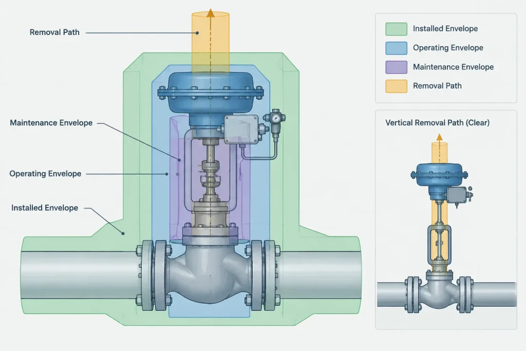
A useful CAD layout separates three different envelopes:
| Envelope | What it represents | Why it matters |
|---|---|---|
| Installed equipment envelope | The physical body, actuator, accessories, and connections | Used for ordinary clash detection |
| Operating envelope | Space needed for stem movement, linkages, indicators, and manual controls | Prevents structures or piping from blocking operation |
| Maintenance envelope | Space needed to remove the actuator, bonnet, trim, or complete valve | Supports planned disassembly and lifting |
A simplified catalog component may be acceptable during early layout, but unresolved envelopes should be marked as provisional. Replacing a preliminary component with vendor geometry should be treated as a controlled model update because the change can affect piping, steel, cable tray, platforms, and lifting access.
Valve Removal and Break-Joint Planning
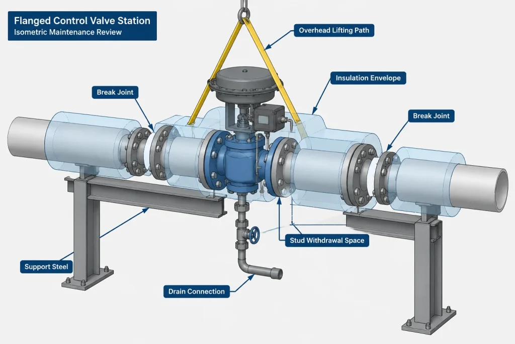
Isolation does not by itself make a control valve removable. The station needs an intentional means of separating the valve from the piping and enough freedom to move it out of position. Flanged ends commonly provide break joints, but the designer must still consider stud withdrawal, gasket access, flange separation, pipe flexibility, and the direction in which the valve will be extracted.
For a heavy valve, identify how lifting equipment can approach and where the suspended load can travel. A clear space above the actuator is not useful if overhead steel prevents a hoist from being installed. Likewise, horizontal extraction may be blocked by a bypass leg that appears clear in plan but crosses the removal path in elevation.
Maintenance access should be evaluated with insulation and removable covers included. The bare-pipe model can conceal conflicts that appear only after the complete operating envelope is shown.
Drains, Vents, and Trapped Sections
Closing upstream and downstream isolation valves can create a trapped section around the control valve. The design may require a means to drain, vent, depressurize, purge, or verify the condition of that section before maintenance. The appropriate connection and destination depend on the service and project requirements.
CAD placement should reflect the intended function. A low-point drain should be evaluated using actual pipe elevations and fitting geometry, not simply placed below the line symbol. A vent should connect where gas can collect. Connections carrying hazardous or valuable process fluid may need closed disposal routing rather than an open termination.
Small-bore branches also need support and protection from accidental loads. Avoid placing them where they become steps, handholds, or obstructions in an access route.
Supports and Loads Around the Station
A control valve station can concentrate weight and introduce forces from actuator mass, valve operation, pipe movement, and connected bypass piping. Supports should not be located solely to make the model look balanced. Their positions and types must be coordinated with the piping support or stress design.
Important layout questions include:
- Can the valve be removed without dismantling a permanent support?
- Does the bypass impose loads on control valve nozzles or adjoining pipe?
- Will thermal movement change alignment at the valve or isolation flanges?
- Does a support obstruct drains, instrument tubing, bolting, or insulation removal?
- Is the actuator’s center of mass adequately considered?
Where structural framing supports the station, allow for base plates, clamps, shoes, and adjustment provisions rather than modeling the pipe directly against an abstract steel surface.
A Practical CAD Review Workflow
- Confirm process sequence. Trace flow through the main line and bypass, including every isolation boundary.
- Place verified interfaces. Establish line centerlines, equipment connections, rack limits, platforms, and structural constraints.
- Model actual component types. Distinguish flanged, welded, threaded, or socket-welded ends and use the selected reducer geometry.
- Add access envelopes. Show operation, actuator travel, bolting, insulation, and removal space.
- Review drainage and venting. Check real elevations and trapped volumes.
- Coordinate supports. Resolve loads, movement, access, and dismantling with the responsible disciplines.
- Compare deliverables. Verify that the P&ID, line list, valve data, model, isometric, and material output describe the same station.
- Record unresolved data. Use project hold or provisional-data procedures for missing vendor dimensions and undecided maintenance requirements.
Typical Layout Errors to Avoid
- Adding a bypass because it appears in a standard detail but is absent from the approved process design
- Routing the bypass across the control valve’s removal path
- Orienting an actuator where it conflicts with steel, flooring, or nearby piping
- Using generic valve dimensions after vendor data becomes available
- Placing isolation valve operators where they cannot be reached safely
- Omitting space for studs, gaskets, insulation, instrument tubing, or lifting equipment
- Creating a drain connection that is not at the physical low point
- Assuming a symmetrical valve body can be installed in either flow direction
- Supporting the station in a way that prevents dismantling
Model the Station as an Operable Assembly
A successful control valve station layout must satisfy process intent, piping geometry, instrument interfaces, structural support, operation, and maintenance at the same time. The valve body is only one part of that problem.
Use generic geometry for early planning only when its limitations are visible and controlled. As project information develops, replace assumptions with approved component data and recheck the station as a complete assembly. The final CAD arrangement should show not merely where the piping fits, but how the station will be operated, isolated, drained, serviced, and removed.
Managing Layout Decisions as the Design Develops
Control valve stations often begin with incomplete equipment information. Preliminary geometry can support routing studies, but the model should clearly distinguish verified data from assumptions. Otherwise, a temporary valve envelope or estimated accessory location may be mistaken for approved design information.
Useful model-status practices include:
- Identifying which valve and actuator geometry is preliminary
- Recording unresolved flow orientation, reducer type, and instrument interfaces
- Showing operating and maintenance space separately from physical equipment
- Tracking bypass, drain, vent, and isolation requirements back to process documents
- Rechecking nearby steel, platforms, cable systems, and piping after vendor geometry is incorporated
Review the Station from Different Working Viewpoints
A station that appears acceptable in an overall model may still fail a task-based review. The designer should examine the arrangement from the viewpoint of the operator, maintenance crew, piping fabricator, instrument technician, support designer, and lifting planner.
Operator viewpoint
Confirm that required controls, indicators, isolation valves, and bypass operators are visible and reachable from an approved access location. Access should not depend on standing on piping, supports, or insulated equipment.
Maintenance viewpoint
Trace the intended disassembly sequence. Confirm that bolting can be withdrawn, joints can be separated, accessories can be disconnected, and the valve or actuator can move from its installed position to a safe handling route.
Fabrication and construction viewpoint
Review weld access, flange assembly, field-fit requirements, temporary supports, installation sequence, and the effect of surrounding construction. A geometrically clear final arrangement may still be difficult to assemble if components cannot be brought into position.
Instrumentation viewpoint
Allow practical routes for tubing, cables, air connections, positioners, and local accessories. These items should remain serviceable without occupying valve operating space or obstructing removal.
Use a Task-Based Final Check
Before releasing the arrangement, walk through the actions the station must support. Consider how personnel will operate the main and bypass valves, isolate and verify the trapped section, disconnect instruments, remove insulation, open break joints, attach lifting equipment, extract the valve, and reinstall the assembly.
This review does not replace formal process, stress, support, instrumentation, structural, safety, or vendor checks. It helps reveal conflicts that ordinary clash detection may miss because an empty space in the model is not necessarily a usable work area.
Control Valve Station Layout FAQ
Does every control valve station need a bypass?
No. A bypass should be included only when required by the approved process design and operating philosophy. A typical arrangement should not override the P&ID or project requirements.
Why is clash detection alone insufficient?
Clash detection generally checks occupied geometry. It may not identify space needed for actuator travel, valve operation, stud withdrawal, flange separation, lifting, insulation removal, or equipment extraction unless those envelopes are intentionally modeled.
What information should control the valve envelope?
Use approved valve and actuator information appropriate to the selected configuration. Body pattern, end connections, actuator arrangement, accessories, and vendor-specific geometry can affect the required space.
Should the bypass be routed above or below the main line?
There is no universal orientation. Routing should reflect process behavior, drainage and venting needs, operator access, support design, maintenance paths, available space, and project requirements.
How should a removal path be represented in CAD?
Show a reserved envelope or controlled clearance zone that reflects the intended extraction direction and handling method. Include relevant accessories, insulation, break-joint activity, nearby structures, and the path to a practical handling area.
When should preliminary geometry be replaced?
Replace it when controlled project or vendor information becomes available. Treat the update as a coordination event and repeat relevant clash, access, support, instrumentation, and maintenance reviews.