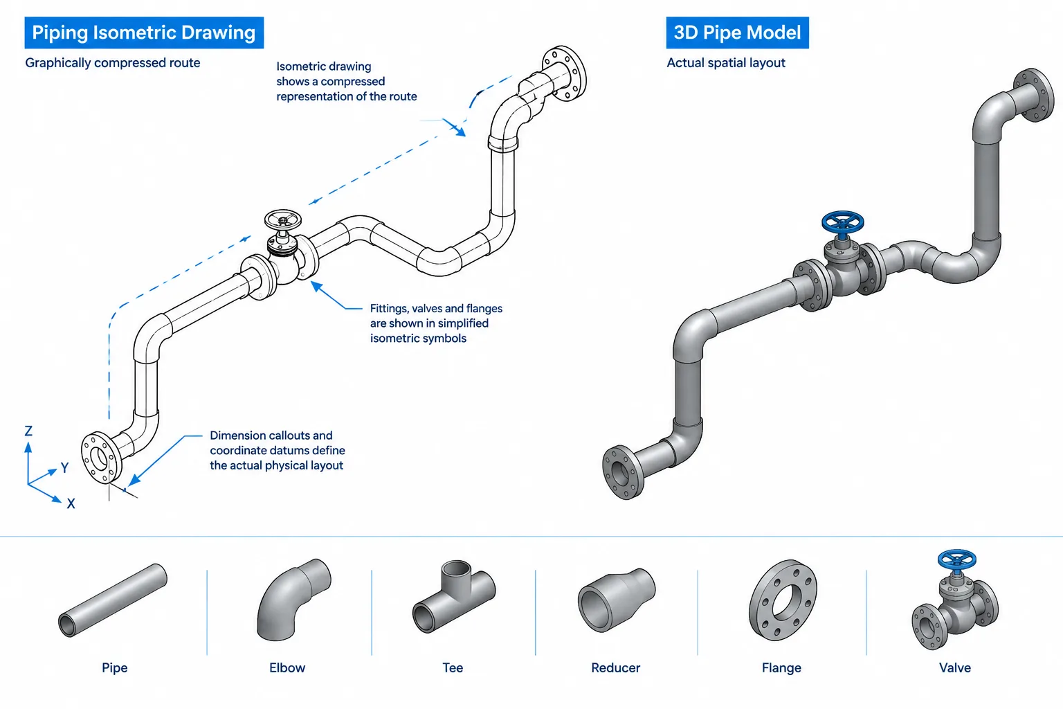
Piping isometric drawings are not measured to scale because their primary purpose is to communicate route, connectivity, dimensions, and fabrication information clearly. The graphic may be stretched, compressed, or rearranged to keep components and annotations readable. Actual pipe geometry must therefore be determined from stated dimensions, coordinates, elevations, reference points, and verified component data rather than from apparent line length.
A piping isometric drawing presents a three-dimensional pipe route on a two-dimensional sheet. It can show direction changes, elevations, fittings, valves, welds, supports, and dimensions in a compact format. However, the apparent length of a line on the sheet is usually not a reliable representation of its real physical length.
This is why piping isometric drawings are commonly treated as not-to-scale documents. Their geometry communicates routing and connectivity, while written dimensions and referenced component data control fabrication and installation. Understanding that distinction is essential when checking pipe cut lengths, locating branches, coordinating tie-ins, or transferring information between a CAD model and an issued drawing.
What “Not to Scale” Means on a Piping Isometric
Not to scale does not mean that the drawing is arbitrary. The route should still be recognizable, connected correctly, and oriented consistently. Components should appear in the proper sequence, branches should leave the correct side of the run, and changes in direction should follow the drawing’s established axes.
The limitation is that graphical distance is not the controlling measurement. A pipe segment that looks short may have a large stated dimension. Another segment may be stretched on the sheet to create room for a valve tag, weld number, support symbol, or bill-of-material reference.
Common reasons for graphical distortion include:
- Fitting a long route onto a practical sheet size.
- Separating crowded fittings and annotations so they remain legible.
- Making small components visible without representing their physical length proportionally.
- Breaking or shortening repetitive straight runs.
- Moving dimensions and notes away from overlapping geometry.
- Showing branches, vents, drains, and instruments clearly.
A scale ruler or CAD distance command applied to the printed linework therefore does not establish the installed dimension unless the drawing has been explicitly produced and controlled for that purpose.
Graphic Geometry Versus Controlling Data
A useful way to read an isometric is to separate the graphic route from the data attached to it. The route answers questions such as “What connects to what?” and “Which direction does the pipe turn?” The dimensions and annotations answer “Where is it?” and “How long is the controlled distance?”
| Drawing information | Primary purpose | Should it be measured graphically? |
|---|---|---|
| Pipe linework | Shows routing, direction, and connectivity | Normally no |
| Written dimensions | Defines controlled distances between identified references | Use the stated value |
| Coordinates and elevations | Locate points within the project coordinate system | Use the stated data |
| Fitting and valve symbols | Identify component type and orientation | Do not infer exact envelope from the symbol |
| Weld and joint symbols | Identify connection locations and fabrication boundaries | Use associated dimensions and component data |
| Break symbols | Indicate that graphical length has been compressed or interrupted | No |
This distinction is particularly important when an isometric uses simplified symbols. A valve body may be drawn larger than its proportional size so its type and operator orientation are visible. An elbow symbol may indicate a change in direction without reproducing the exact fitting envelope. The actual component geometry must come from verified dimensional data applicable to the selected item.
Why Diagonal Lines Can Be Misleading
In an isometric view, plant directions are represented by drawing axes rather than by a plan view and elevation view placed side by side. A route can therefore appear diagonal on the sheet even though it runs horizontally in a single plant direction. A vertical segment is normally recognizable as vertical, but horizontal directions are conventionally inclined on the page.
Offsets require additional care. A sloping line on the sheet might represent a simple horizontal run along an isometric axis, a true vertical change, or a compound offset involving changes in more than one coordinate direction. Its appearance alone does not provide enough information to calculate the pipe length.
For a compound route, the reader should identify the coordinate changes or stated offset dimensions. The true centerline travel must be derived from those controlled values and the actual fitting arrangement, not from the line’s paper length.
Which References Control Pipe Length?
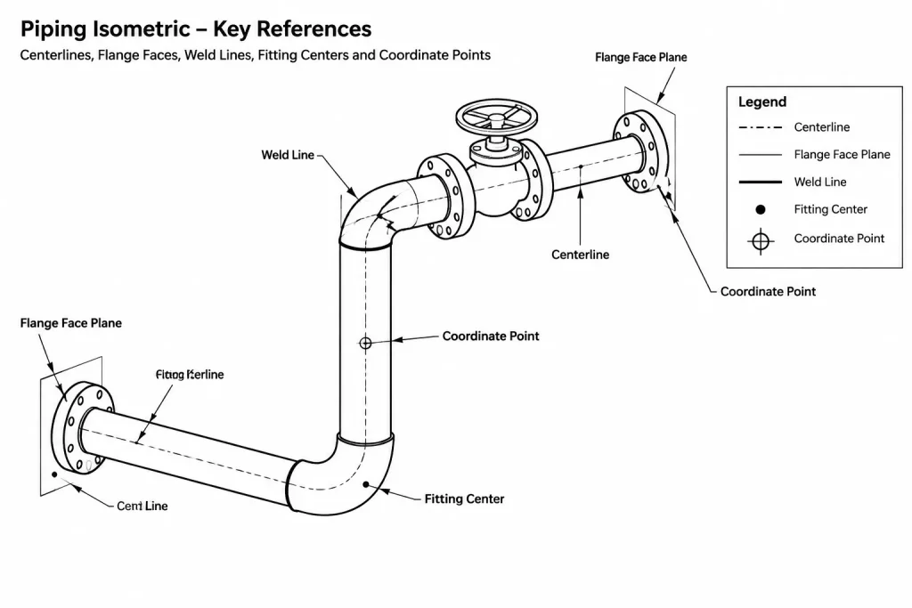
Before using an isometric dimension, identify its endpoints. A dimension can refer to fitting centerlines, flange faces, weld lines, equipment nozzle faces, branch centerlines, tie-in points, or project coordinates. These references are not interchangeable.
For example, a center-to-center dimension between elbows is not the same as the straight pipe cut length between them. To obtain the cut length, the applicable fitting takeoffs and joint details must be considered. Similarly, a face-to-face dimension across a valve station may include valve and gasket-related geometry that cannot be assigned to the connecting pipe.
The controlling reference hierarchy depends on the project, but a sound review generally considers:
- Issued dimensions and coordinate callouts on the drawing.
- Verified component dimensions from the applicable project catalog or approved manufacturer data.
- Defined fitting takeoffs and end-connection geometry.
- Project rules for weld gaps, socket engagement, threaded makeup, or field-fit allowances.
- Explicit notes identifying dimensions that require field verification.
If these inputs conflict, the discrepancy should be resolved rather than hidden by adjusting the graphical linework.
How CAD Generation Can Create a Distorted Isometric
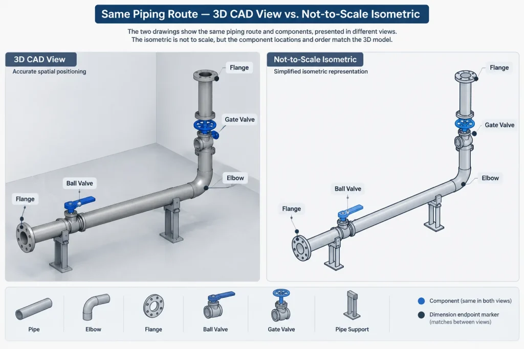
A piping isometric may be extracted from an accurately positioned three-dimensional model and still be graphically not to scale. During drawing generation, the software can reposition symbols, spread annotations, compress long straight runs, or introduce breaks to produce a readable sheet.
This does not necessarily indicate an inaccurate model. It reflects the different purposes of the model and the deliverable:
- The model manages physical position, component geometry, connectivity, and spatial coordination.
- The isometric communicates the information needed for fabrication, examination, installation, and material control in a compact drawing.
Problems arise when users treat the extracted sheet as if it were a scaled model view. Editing generated linework manually can also create a mismatch: the drawing may look correct while its dimensions, material data, or model relationships remain unchanged. Where possible, routing or component corrections should be made in the controlled source and the isometric regenerated according to the project workflow.
A Practical Checking Workflow
1. Confirm the route and component sequence
Trace the line from one defined endpoint to the other. Check reducers, valves, branches, flanges, specialty items, and terminal connections in order. This verifies topology before dimensional checking begins.
2. Identify the directional basis
Use the north arrow, coordinate labels, elevation references, or project orientation convention. Do not assume that a line rising on the sheet rises physically.
3. Mark dimension endpoints
Determine whether each dimension terminates at a centerline, face, weld, coordinate point, or other datum. Ambiguous endpoint graphics should be clarified.
4. Reconcile coordinates and dimensions
Where both are supplied, verify that coordinate differences are consistent with the dimensioned route. Account for changes in direction and for dimensions that apply only to one coordinate axis rather than to total pipe travel.
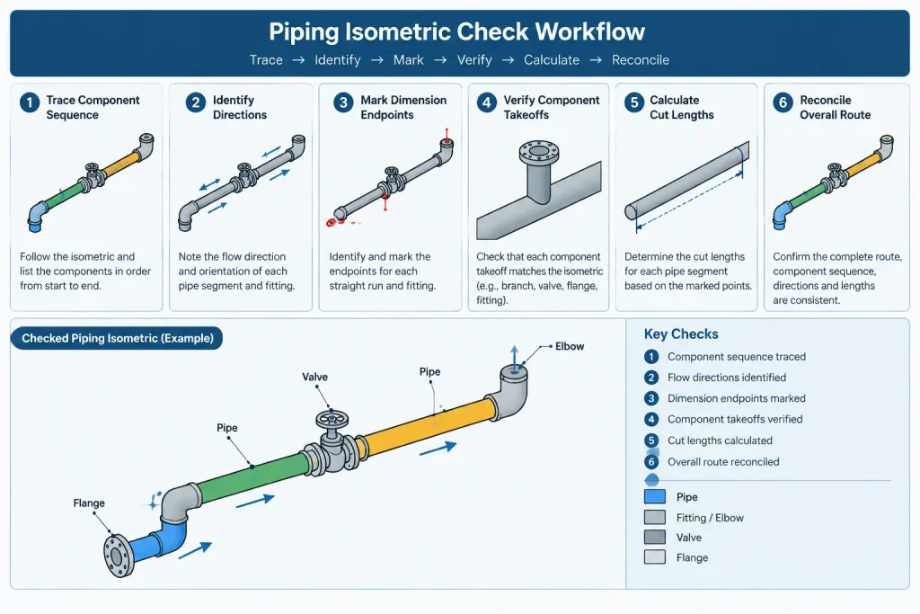
5. Check component takeoffs
Use verified catalog or project data for elbows, tees, reducers, flanges, valves, and specialty components. Do not estimate takeoffs by measuring their symbols.
6. Review cut lengths and closure conditions
Confirm how fitting takeoffs, end preparations, assembly allowances, field-fit areas, and closure welds affect each straight piece. Distinguish calculated pipe cut length from overall spool dimensions.
7. Perform an independent total check
For a route between known interfaces, compare the sum of relevant component lengths and pipe segments with the controlled overall distance. This can reveal omitted fittings, duplicated allowances, or dimensions tied to the wrong reference plane.
Common Errors Caused by Measuring the Picture
- Estimating an undimensioned spool: A user scales the graphic to infer a missing value, even though different parts of the drawing have been compressed differently.
- Assuming symbol size equals component size: A valve or flange symbol is used as an envelope instead of checking verified dimensions.
- Misreading direction: A horizontal isometric axis is interpreted as a physical slope or elevation change.
- Using center-to-center distance as cut length: Fitting takeoffs and joint geometry are not deducted.
- Ignoring breaks: A broken straight run is assumed to represent a small omitted distance rather than a dimension-controlled length.
- Trusting visual alignment over coordinates: Two items that appear aligned on the sheet may occupy different plant coordinates.
When the Drawing Does Not Provide Enough Information
An undimensioned segment should not be resolved by scaling the isometric. Instead, check whether its location is defined by adjacent coordinates, an overall dimension, a referenced detail, equipment interface data, or the controlled model. If the value still cannot be established, it is a documentation gap that requires clarification.
The same caution applies to generic CAD blocks and symbols. They can communicate component type and connection arrangement, but they do not become project-specific dimensional definitions merely because they are inserted into a drawing. Their geometry must be checked against the selected component and governing project data.
Key Takeaway
A piping isometric is a data-rich route diagram, not a picture to be measured. Read the linework for connectivity and orientation, then use written dimensions, coordinates, elevations, reference planes, and verified component data for physical values. Treating the graphical layout and the controlling dimensions as separate layers of information leads to more reliable fabrication checks, clearer CAD revisions, and fewer field-fit surprises.
Use the Isometric as a Controlled Technical Document
The practical issue is not whether the drawing looks proportional, but whether every required fabrication or installation value can be traced to controlled information. A checker should be able to identify the endpoints of each dimension, the references that locate the route, and the component data used to calculate straight pipe pieces.
When information is missing or conflicting, visually scaling the linework creates an unsupported assumption. The appropriate response is to compare the isometric with the controlled model, equipment connection information, referenced details, and approved component records. Any unresolved discrepancy should follow the project clarification and revision process.
Keep Graphic Changes and Data Changes Together
A manual redline or CAD edit can improve the appearance of an isometric without correcting the underlying route or associated data. Changes to component sequence, orientation, dimensions, coordinates, or connection points should be evaluated together so that the drawing does not communicate conflicting instructions.
This distinction is especially important during interdisciplinary review. Layout personnel may focus on spatial position, fabricators on cut lengths and joints, and field personnel on tie-ins and installation references. Each group should rely on the same controlled dimensions and datums rather than independently interpreting graphical distance.
Questions to Ask Before Releasing an Isometric
- Are the route and component sequence unambiguous?
- Can each controlling dimension be traced to clearly identified endpoints?
- Are coordinates and elevations consistent with the intended plant orientation?
- Have component takeoffs been obtained from verified project data rather than symbol size?
- Are breaks, field-fit areas, tie-ins, and special connection conditions clearly identified?
- Have drawing changes been reconciled with the controlled model or other governing source?
A visually distorted isometric can still be technically complete. A visually neat isometric can still be inadequate if its dimensions, references, or component data are missing or inconsistent.
Frequently Asked Questions
Can a scale ruler be used on a piping isometric?
Normally, no. The apparent length of the linework may have been altered for sheet layout and annotation clearance. Use the stated dimensions and controlled references instead.
Does not to scale mean the route direction is inaccurate?
No. The drawing should still communicate the intended component sequence, branch orientation, and route directions. Not to scale means graphical distance is not the controlling physical measurement.
Can an isometric generated from an accurate model still be distorted?
Yes. Drawing-generation tools may rearrange symbols, compress straight runs, or spread crowded items while retaining model-derived dimensions and connectivity.
How should an undimensioned pipe segment be determined?
Check adjacent coordinates, overall dimensions, equipment interfaces, referenced details, and the controlled model. If these sources do not establish the value, request clarification rather than measuring the picture.
Why is a center-to-center dimension not automatically a pipe cut length?
The dimension may include space occupied by fittings or other components. Straight pipe cut length depends on the identified reference points, applicable component takeoffs, end connections, and project fabrication requirements.
Do valve and fitting symbols show exact component dimensions?
Not necessarily. Symbols primarily identify component type, location, and orientation. Exact geometry should come from verified data for the selected component.