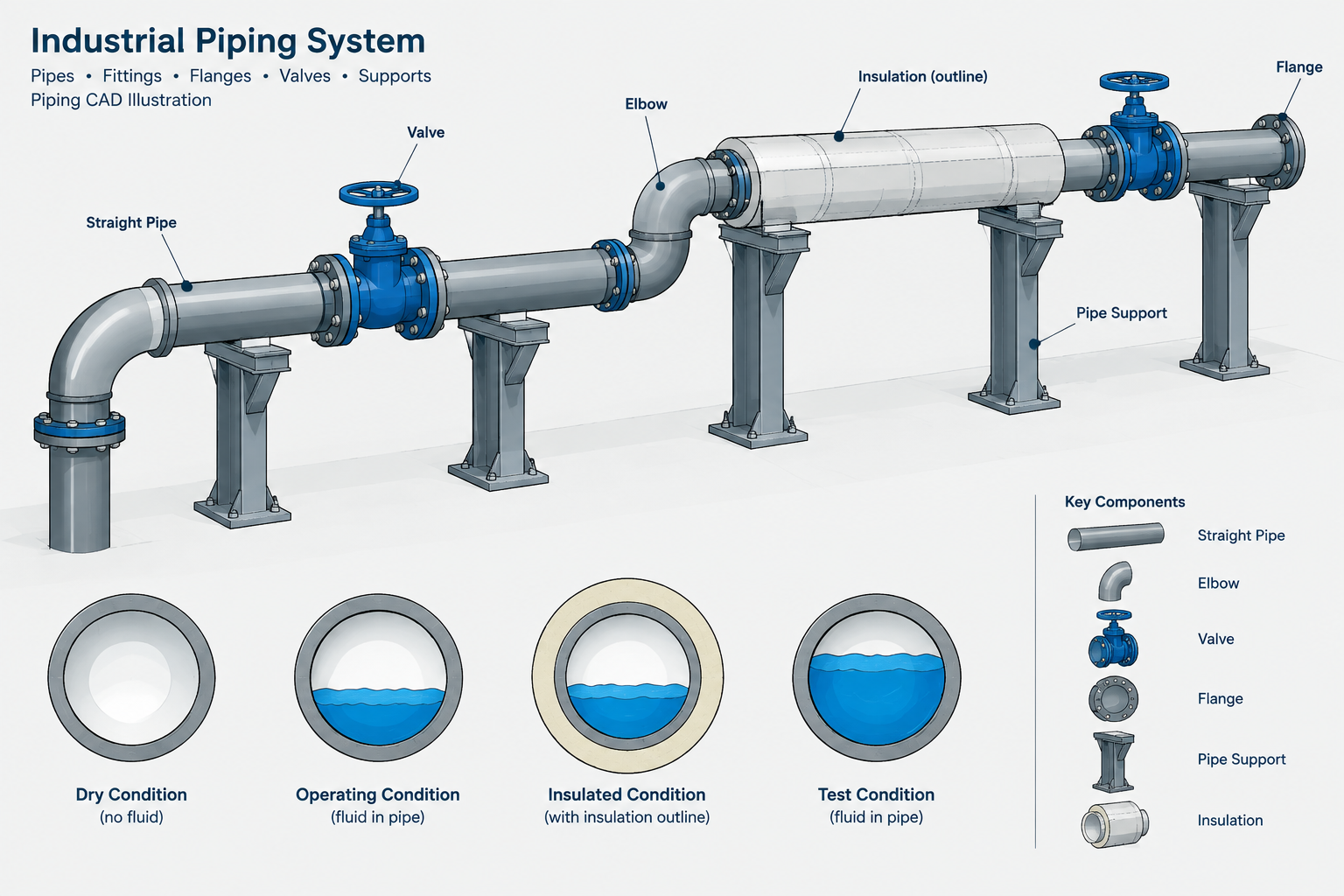
Piping weight data in CAD is useful only when the load condition and inclusion basis travel with the reported value. A model total without that context can be misread as an empty-system weight, an operating load, or a test condition.
This reference helps CAD users and engineering reviewers distinguish those cases, identify distributed and concentrated loads, and document model-derived information for support, stress, structural, and equipment-interface reviews.
A pipe route that fits geometrically may still be incomplete from a support and structural coordination standpoint. Engineers evaluating supports, steel, equipment nozzles, and building interfaces need to know what the piping system weighs under relevant conditions. The CAD model can help provide that information, but only when each weight value has a clearly defined basis.
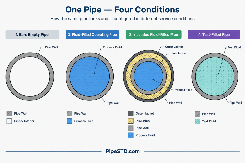
Piping weight is not one universal number. An empty line, a line filled with process fluid, an insulated line, and a line filled for testing represent different loading conditions. Valves, flanges, strainers, actuators, and specialty items can also create concentrated loads that are easy to overlook when attention is focused only on straight pipe.
This guide explains the common weight categories, how they relate to CAD data, and how to prepare a reliable handoff without treating an unverified model calculation as final engineering output.
Why the weight basis matters
A note that says only “pipe weight” is ambiguous. It might mean bare pipe, the complete installed assembly, or an operating line containing fluid. Those interpretations can produce significantly different support reactions, especially on large lines, thick-wall pipe, heavily insulated systems, or routes containing several inline components.
Weight information may be used for:
- Preliminary support placement and support-type selection
- Pipe rack and platform coordination
- Structural load summaries
- Equipment nozzle-load reviews
- Spring support or variable support studies
- Transport and lifting planning for fabricated spools
- Comparison of operating and testing conditions
- Checking concentrated loads near branches and equipment
CAD users do not necessarily own every load calculation, but they often control the geometry and component data from which those calculations begin. Clear classifications prevent downstream users from applying the wrong weight case.
Common piping weight conditions
| Weight condition | Typical contents | Important limitation |
|---|---|---|
| Dry or empty | Pipe and identified piping components without process or test fluid | May exclude insulation, lining, tracing, coatings, or attachments unless stated |
| Operating | Installed piping plus the fluid expected during the defined operating case | Fluid density and fill condition must be identified by the responsible discipline |
| Insulated operating | Operating case plus insulation, jacketing, and other included external systems | Insulation thickness and density cannot be assumed from graphics alone |
| Test | Installed system plus the specified test medium | The test medium and actual test boundary may differ from normal operation |
| Spool or shipping | Items physically included in a fabricated or transported assembly | Loose items, temporary attachments, and field-installed components require separate treatment |
Dry or empty weight
Dry weight usually begins with the metal mass of straight pipe and permanently installed components. Depending on project practice, the term may or may not include insulation, lining, tracing, coatings, support attachments, or valve operators. The qualifier is therefore more important than the label itself.
A useful CAD data field should state the inclusion basis, such as bare pipe and components or installed empty assembly. Avoid expecting another discipline to infer the meaning from a single weight column.
Operating weight
Operating weight adds the contents present during a defined operating condition. The fluid contribution depends on the pipe’s internal volume, fluid density, and actual fill condition. Internal diameter matters here; nominal pipe size or outside diameter alone is not enough to establish contained volume.
Some systems may be fully flooded, while others may contain vapor, mixed phases, intermittent liquid, or deposited material. Process engineering input is needed when the condition cannot be represented as a simple, completely filled line.
Insulated weight
Insulation is external to the pipe but contributes a distributed load along the route. Jacketing, vapor barriers, heat tracing, protective coverings, and removable insulation boxes may also add weight. These items are often simplified or omitted from the visible CAD geometry, so visual review alone cannot confirm that they are included in a weight report.
The insulation basis should come from controlled project data. A generic graphical insulation thickness should not be converted into an engineering load unless its material and inclusion assumptions have been verified.
Test weight
A test condition can govern support or structural checks when the test medium is heavier than the normal operating contents or when a normally empty system is temporarily filled. The CAD team should not assume that every modeled line is tested with the same medium or as one continuous boundary.
Test packages may split a system at blinds, valves, temporary closures, equipment boundaries, or other isolation points. If the test boundary is not represented correctly, a load summary may include piping that is not filled or omit piping that is.
Distributed loads and concentrated loads
Straight pipe, contained fluid, and continuous insulation are commonly treated as distributed weight along the pipe centerline. Inline equipment and heavy fittings create more localized effects. Both categories matter, but they should not be confused.
Potential concentrated loads include:
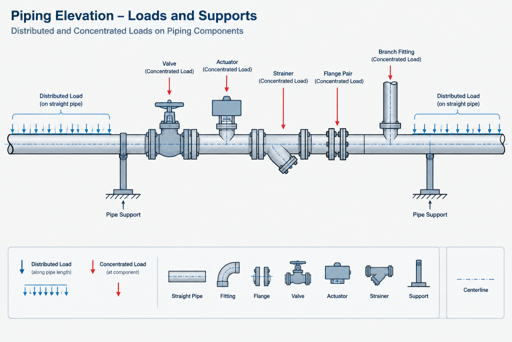
- Valves and valve actuators
- Strainers and filters
- Flanged joints and blind flanges
- Large branch fittings
- Specialty items and inline instruments
- Removable spool pieces
- Temporary test blinds or test equipment
- Field-mounted accessories supported by the pipe
A model that assigns an average weight per unit length to the entire route may reproduce total line weight while still placing the load incorrectly. Support reactions depend on where heavy items are located relative to supports, branches, and equipment nozzles.
How CAD systems typically derive weight
For straight pipe, the basic logic uses material volume and material density. The metal cross-sectional area is based on outside diameter and wall thickness, and that area is applied over the modeled length. Contained fluid is based on internal cross-sectional area, filled length, and fluid density.
Conceptually:
- Pipe metal weight depends on pipe geometry, length, and material density.
- Fluid weight depends on internal volume, fill condition, and fluid density.
- Insulation weight depends on its annular volume, density, and included coverings.
- Component weight normally comes from verified catalog, manufacturer, or project data.
This simple description hides several practical risks. Modeled centerline length may not equal purchased pipe length. Fitting geometry can overlap straight pipe geometry. A component may have a placeholder weight, a missing weight, or a value copied from a different size or configuration. Duplicate geometry can also create double counting.
Data fields worth controlling
A weight report is easier to audit when its source fields are explicit. Useful fields may include:
- Line number or system identifier
- Component tag or unique model identifier
- Nominal size and pipe schedule or wall designation
- Material specification reference
- Component type and end connection
- Modeled length where applicable
- Dry component weight
- Fluid or test-medium basis
- Insulation inclusion status
- Weight-data source and verification status
- Applicable operating or test case
Not every project uses the same property names. The important practice is to separate geometry, physical-property inputs, and calculated results rather than hiding them in one unqualified value.
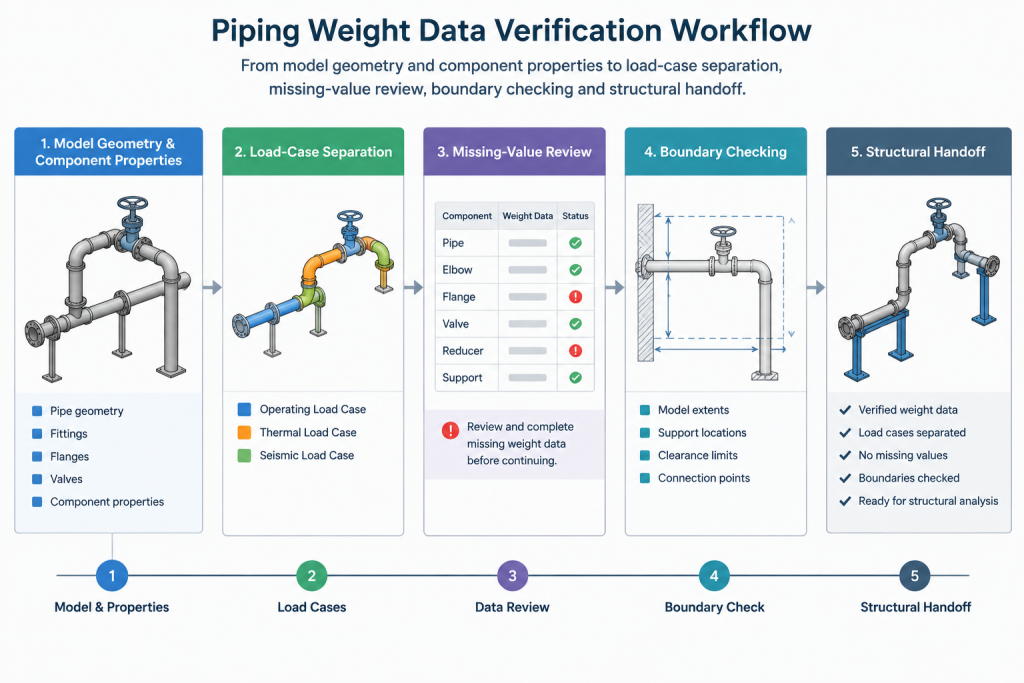
A practical CAD weight-check workflow
1. Define the reporting boundary
Identify whether the report covers a line, test package, rack segment, spool, area, or complete system. Confirm how branch lines and continuation points are handled so that segments are neither omitted nor counted twice.
2. Confirm the component population
Review the route for valves, specialty items, reducers, branches, flanges, blinds, and inline instruments. Check whether each item is a real model component or merely drawn as generic geometry. Generic solids and drafting symbols may not carry usable weight properties.
3. Validate pipe geometry inputs
Confirm that nominal size, wall designation, material, and modeled length are populated consistently. Incorrect wall data affects both pipe metal weight and internal volume.
4. Separate the load cases
Generate or organize dry, operating, insulated, and test conditions separately. Do not overwrite one case with another or combine them without a clear calculation basis.
5. Review missing and suspicious values
Filter for blank, zero, placeholder, or unusually repeated component weights. A missing value should remain visibly unresolved rather than being silently treated as zero. Compare similar components to locate obvious mapping errors, but do not replace verified data with an unsupported estimate.
6. Check load location as well as total weight
Review heavy components in the model and confirm their relationship to nearby supports and equipment. A plausible total weight does not prove that the spatial distribution is correct.
7. Record assumptions and issue status
State the model revision, report boundary, included items, excluded items, fluid basis, insulation basis, and unresolved data. Mark preliminary values accordingly. Structural or stress reviewers should be able to understand what the report represents without reopening every component property.
Common mistakes to avoid
- Using outside diameter to calculate fluid volume
- Assuming nominal pipe size is the actual internal diameter
- Applying one fluid density to unrelated line services
- Treating all operating lines as completely liquid-filled
- Omitting actuators because only valve-body weight is stored
- Counting insulation geometry and a separate insulation allowance twice
- Using generic component weights across different sizes or configurations
- Ignoring temporary test items and altered test boundaries
- Reporting totals without identifying the model revision
- Presenting preliminary CAD output as a verified support load
What a useful weight handoff should say
A practical handoff is more than a spreadsheet total. It identifies the load condition, system boundary, data sources, excluded items, unresolved components, and model revision. Where possible, it preserves component identifiers so reviewers can trace a reported load back to its position in the model.
CAD-generated weight data is most valuable when it is transparent and repeatable. The model can organize geometry, lengths, component locations, and controlled properties, but the resulting loads still require verification against project specifications, process conditions, vendor information, and the intended analysis case. Clear weight categories make that verification faster and reduce the risk of a dry, operating, or test load being used for the wrong purpose.
How to interpret a CAD weight report
A load-case name should be treated as a definition, not merely a report label. Before using a result, confirm what physical items are included, which system boundary was selected, and whether unresolved model properties remain in the calculation.
Also verify the reporting convention. CAD databases and project documents may use the terms mass and weight inconsistently. The handoff should identify the units and convention being reported rather than expecting reviewers to infer them from a column heading.
Reconcile geometry, component data, and case assumptions
A dependable review compares three related information sets: modeled geometry, component records, and load-case assumptions. Geometry establishes location and route length. Component records provide item identity and controlled physical properties. Case assumptions determine contents, insulation status, test boundaries, and other inclusions.
Agreement in only one area is not sufficient. A complete-looking route can contain components with missing properties, while a plausible total can still place concentrated loads incorrectly. Likewise, verified component weights do not correct an inaccurate fill boundary or duplicated model geometry.
Keep discipline responsibilities visible
Project responsibilities vary, but weight preparation commonly depends on input from several disciplines. CAD or design personnel maintain geometry and component identity. Process information establishes operating contents and fill conditions. Project specifications define piping and insulation requirements. Vendor information may be needed for valves, actuators, and specialty equipment. Stress and structural reviewers then apply the accepted cases to the intended analysis.
The handoff should identify which inputs are verified, which are preliminary, and which require action from another discipline. This is safer than filling data gaps with unsupported assumptions.
Release checks for model-derived weight data
- Use a distinct name and definition for each load condition.
- State the modeled system, line, spool, area, or test boundary covered by the report.
- Identify whether insulation, tracing, lining, coatings, operators, attachments, and temporary items are included.
- Preserve component identifiers so reported loads can be located in the model.
- Flag missing, placeholder, or unverified properties rather than treating them as confirmed values.
- State the model revision and report status.
- Document the reporting units and whether the stored property represents mass or an applied weight convention.
- Keep load cases separate unless the approved calculation method specifically combines them.
These controls make the report auditable without implying that CAD output replaces support, stress, structural, process, or vendor verification.
Frequently asked questions
Is CAD-calculated piping weight the same as a support load?
No. CAD data can provide component weights, distributed loads, and load locations, but a support reaction depends on the piping arrangement, support conditions, load case, and analysis method. The model output is an input to the engineering review, not automatically the final support load.
Can dry weight, fluid weight, and insulation weight simply be added together?
They can be combined only when the values use the same boundary and compatible assumptions, and when their scopes do not overlap. A combined result may be wrong if a component value already includes insulation, contents, attachments, or another allowance also reported separately.
Does visible insulation geometry prove that insulation weight is included?
No. Insulation may be shown symbolically, generated from a graphical rule, or excluded from physical-property calculations. Its material basis and inclusion status must be confirmed in controlled project data.
Why can a correct total weight still produce a poor engineering handoff?
Total weight does not show where the load acts. Averaging a heavy valve, actuator, strainer, or specialty item across an entire route can hide the localized effect near supports, branches, or equipment connections.
How should missing component weights be handled?
Keep them visible as unresolved data and identify the affected components. Do not silently convert blanks to zero or replace them with an unsupported generic value. Obtain verified project, catalog, or vendor information through the applicable review process.
Can the operating condition be used as the test condition?
Not by assumption. The medium, fill boundary, temporary isolation, and included equipment may differ. Test loading should follow the defined test package and the approved engineering basis.