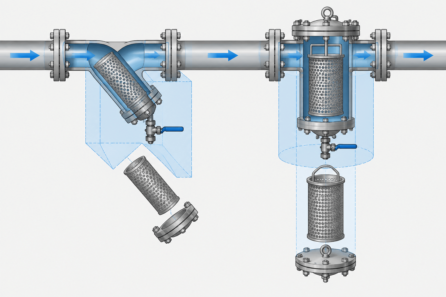
Comparing Y-strainers vs. basket strainers in piping CAD requires more than choosing the correct body symbol. The model must communicate how fluid enters and leaves, where debris collects, how the closure is accessed, and in which direction the screen or basket is removed.
This guide focuses on the layout and drafting decisions that help prevent orientation conflicts, blocked maintenance paths, and unsupported assumptions. It complements, but does not replace, the approved piping documents and manufacturer information for the selected strainer.
Strainers remove debris from a flowing piping system before the debris can damage pumps, valves, instruments, traps, spray devices, or other sensitive equipment. Although a strainer may appear to be a simple inline component, its body orientation, removal direction, drain arrangement, and maintenance envelope can significantly affect a piping layout.
The choice between a Y-strainer and a basket strainer is not merely a symbol-selection decision. Each type creates different layout and maintenance constraints. A useful CAD model or drawing must therefore communicate more than line size and end connections: it should preserve flow direction, show the screening chamber correctly, and reserve enough space for servicing the internal element.
Basic Difference Between Y-Strainers and Basket Strainers
A Y-strainer has an angled branch that contains the screen or perforated element. Its compact body often makes it practical where space is limited or where the strainer is treated as a relatively small inline component. Depending on the selected product and service, the branch may also include a plug, drain, blowoff connection, or valve.
A basket strainer uses a larger chamber containing a removable basket. The chamber is commonly accessed through a cover, allowing the basket to be lifted or withdrawn for cleaning. Basket strainers can provide a larger debris-holding area, but their bodies and maintenance envelopes may require substantially more layout space.
Neither type should be selected from geometry alone. Process conditions, allowable pressure loss, expected debris loading, cleaning frequency, piping specification, material requirements, end connections, and approved manufacturer data all influence the final choice.
| Layout consideration | Y-strainer | Basket strainer |
|---|---|---|
| Body form | Inline body with an angled screening leg | Enlarged chamber containing a removable basket |
| Typical CAD concern | Branch direction and access to the closure | Cover access and basket-removal clearance |
| Space behavior | Usually compact along the pipe run | Often requires more surrounding space |
| Debris removal | Screen cleaning or removal through the angled leg | Basket removal through the chamber cover |
| Drain or blowoff | May be provided at the screening leg | May be provided at a low point in the body |
| Critical verification | Permitted installation orientation | Cover and basket withdrawal direction |
These are general distinctions rather than universal product rules. Actual construction and allowable mounting positions must be checked against the selected component documentation.
Why Orientation Matters
The screening chamber is intended to collect debris in a location where it can be retained and removed. Rotating a strainer only to make the model look orderly may interfere with that function or make the element difficult to service.

Y-Strainer Branch Position
On a horizontal pipe, a Y-strainer is often arranged so debris can settle into the screening leg instead of returning immediately to the flow path. However, the suitable branch position can depend on whether the fluid is liquid, gas, steam, or another service. Condensate behavior, pocket formation, drainage, and access may all affect the orientation.
Installation in a vertical line requires additional verification. Flow direction and product design determine whether debris will remain in the collection area and whether the screen can be removed safely. A generic CAD block should not imply that every Y-strainer may be installed in every rotational position.
Basket Strainer Chamber Position
A basket strainer is commonly modeled with its chamber and removable cover in the manufacturer-defined operating orientation. The cover location establishes the direction from which personnel must access the basket. If nearby piping, structural steel, cable tray, or equipment blocks that direction, routine cleaning may become impractical even though the pipe centerlines fit.
Designers should avoid mirroring or rotating a basket-strainer model without confirming that the modified orientation is permitted. Drain locations, internal basket seating, venting, and cover handling may be orientation-dependent.
Flow Direction Is Part of the Component Definition
Many strainers are directional. Their internal geometry routes fluid through the screen in a defined manner, so reversing the body can change how debris is captured and may prevent proper operation.
In CAD, flow direction should be coordinated across the P&ID, piping model, isometric, and equipment arrangement. Do not rely solely on the visual shape of a simplified block. Useful checks include:
- Confirm the process flow direction from current engineering documents.
- Compare it with the arrow or inlet and outlet identification in approved product data.
- Orient the 3D component or drawing block accordingly.
- Verify that the isometric flow arrow does not conflict with the component orientation.
- Check that drains, vents, and cleaning access remain usable after orientation.
If the exact strainer has not been selected, mark the geometry as preliminary and avoid treating a generic body as fabrication-ready dimensional data.
Model the Maintenance Envelope, Not Just the Body
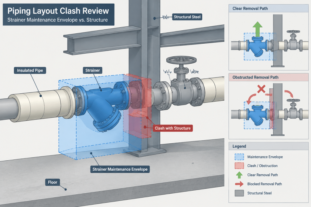
A common layout error is checking only for interference with the installed strainer body. Maintenance may require a larger temporary space than normal operation.
For a Y-strainer, the screen or closure may need to move outward along the axis of the angled leg. The necessary envelope can conflict with a floor, wall, pipe rack member, neighboring valve, insulation, or another line. Access for tools and safe handling should also be considered.
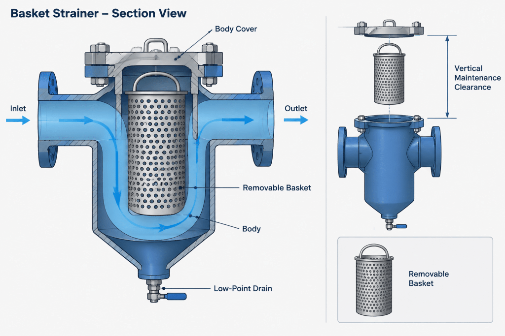
For a basket strainer, the cover must first be opened or removed, after which the basket needs a clear withdrawal path. The required space may extend above or beside the body according to the design. Larger covers may also require a handling method that affects the surrounding arrangement.
A practical CAD convention is to place maintenance volumes on a dedicated, non-plotting layer or in a clearly classified model object. This allows clash reviews to distinguish permanent steel-to-steel interference from an access obstruction. The envelope should be based on verified vendor information when available, not an arbitrary offset.
Drains, Blowoff Connections, and Safe Routing
A strainer connection at the bottom of a chamber may be used for draining, flushing, or blowing down collected material, but its purpose should not be assumed from shape alone. The piping specification, process documentation, and approved component details should define the intended arrangement.
When a drain or blowoff line is required, the CAD layout should address:
- Connection size, type, rating, and material class from controlled project data.
- Valve accessibility and operating direction.
- Discharge destination and any requirement for a closed collection system.
- Potential release of pressure, temperature, hazardous fluid, or solids.
- Low-point drainage and avoidance of unintended liquid pockets.
- Space to remove the screen or basket without dismantling the drain unnecessarily.
A small connection should not be drawn as an unreviewed open-ended stub simply because that arrangement appears in a generic detail. The discharge method is a process and safety decision.
End Connections and Overall Length
Y-strainers and basket strainers may be supplied with different end arrangements, including flanged, threaded, socket-weld, butt-weld, or other project-approved connections. Changing the connection type can alter overall length, joint geometry, assembly sequence, and maintenance strategy.
A symbolic P&ID representation does not establish the face-to-face or end-to-end dimension. Likewise, a generic 3D library component may have approximately correct proportions without matching the purchased item. Before issuing fabrication drawings, verify the selected size, end connection, pressure designation, material, body orientation, and dimensional data against controlled project and manufacturer information.
For flanged strainers, the model should also account for flange joints, gaskets, bolting access, and the ability to separate the assembly if removal is expected. Welded-end strainers require a different replacement and maintenance plan because the body cannot be released by simply unbolting its ends.
Simplex, Duplex, and Temporary Strainers
A simplex basket strainer has one active chamber and generally requires an operational plan for cleaning or isolation. A duplex arrangement uses multiple chambers with a switching mechanism so flow can be redirected during servicing, subject to the actual design and operating procedure. A duplex strainer is therefore not just two simplex bodies placed side by side; it should be modeled as the selected assembly with its own connections, operating space, and valve or transfer mechanism.
Temporary startup strainers, such as cone or basket forms installed within a piping joint, are a separate detailing problem. They may have little external geometry but still require identification, installation direction, pressure-loss review, and a documented removal or retention decision. They should not be confused with permanent basket-strainer bodies in the material list.
Recommended CAD Data for a Strainer
A strainer object or equipment record should carry enough information to coordinate the physical component without embedding unverified assumptions. Useful fields include:
- Tag or component identifier.
- Strainer type and service description.
- Nominal line size and reducer information, if applicable.
- End-connection type and pressure designation.
- Material class or specification reference.
- Flow direction.
- Required installation orientation.
- Drain, vent, or blowoff connection data.
- Vendor and model status, such as generic, proposed, or approved.
- Overall dimensions and maintenance clearances when verified.
- Screen or basket removal direction.
Screen mesh, perforation, or opening information may be important to process and mechanical selection, but it should come from the responsible engineering documents. It should not be inferred from the CAD graphic.
CAD Review Checklist
- Is the strainer type consistent with the P&ID and line documentation?
- Does the modeled inlet-to-outlet direction match process flow?
- Is the body installed in a permitted orientation?
- Can the screen, basket, and cover be removed?
- Are tool access and cover-handling needs represented?
- Do insulation and tracing affect access to the closure?
- Are drains, vents, and blowoff lines connected to an approved destination?
- Are flange joints or other end connections modeled consistently with the piping class?
- Does the component dimension match verified vendor data?
- Can the strainer be isolated and serviced according to the intended operating plan?
- Are temporary strainers identified separately from permanent components?
Practical Takeaway
The central difference in a Y-strainer vs. basket strainer CAD layout is not simply the body shape. A Y-strainer concentrates attention on the angled screening leg, its permitted orientation, and the screen-removal path. A basket strainer requires careful treatment of the chamber cover, basket withdrawal, body support, and surrounding service space.
Use generic geometry during early routing only when its preliminary status is clear. As selection progresses, replace assumptions with verified connection, orientation, dimensional, and maintenance information. That workflow helps prevent a compact model from becoming an inaccessible or incorrectly installed field assembly.
Applying the Comparison During Design Development
The appropriate level of CAD detail changes as a project develops. During early routing, a generic strainer object may be sufficient to reserve approximate space and communicate flow direction. Once a component is proposed or approved, the generic object should be reviewed against controlled dimensional, connection, orientation, and maintenance information.
Keep the status of the model clear. A visually detailed component can still be preliminary, while a simple representation may be reliable if its key interfaces have been verified. Geometry should not be treated as vendor-approved merely because it looks complete.
Coordinate the Same Intent Across Deliverables
The P&ID, piping model, isometric, line documentation, and maintenance review should describe the same functional arrangement. Differences between these deliverables often reveal reversed flow, an incorrect branch position, a missing drain connection, or an inaccessible cover before fabrication information is released.
- P&ID: Confirm the strainer type, tag, process flow, and required auxiliary connections.
- Layout model: Check body orientation, surrounding access, support interfaces, and removal paths.
- Isometric: Confirm component direction, end connections, and consistency with the routed line.
- Maintenance review: Evaluate closure operation, element withdrawal, tool access, isolation, and handling needs.
- Procurement or vendor review: Replace generic assumptions with approved component information.
Separate Hard Clashes From Service Conflicts
A strainer body can be free of physical clashes while remaining impossible to maintain. CAD review should distinguish permanent component interference from temporary service-space conflicts. A removable screen, basket, cover, tool, or handling path may pass through space that appears empty during normal operation.
Representing that service space as a separate model object or controlled layer makes the design intent easier to review. Its shape and direction should follow verified removal information rather than a standard clearance applied to every strainer.
Record Unresolved Items Explicitly
If the manufacturer, model, or final arrangement is not yet known, document the uncertainty instead of embedding it silently in the geometry. Open items may include permitted mounting position, closure direction, drain purpose, support requirements, insulation access, or the method used to remove the internal element.
This approach allows routing work to continue while preventing preliminary geometry from being mistaken for fabrication-ready information.
Frequently Asked Questions
Can a Y-strainer CAD block be rotated to fit the available space?
Only after confirming that the resulting orientation is permitted for the selected product and service. Rotation can affect debris collection, drainage, screen access, and the behavior of the process fluid.
What is the main maintenance-space difference between the two types?
A Y-strainer generally requires access along the screening-leg closure and removal direction. A basket strainer requires access to its chamber cover and a clear path for withdrawing the basket. The actual envelope depends on the selected construction.
Should a generic CAD model include drain or blowoff piping?
It may show a connection when that connection is supported by controlled project information, but its purpose and discharge arrangement should not be inferred from body shape. Drain, flush, and blowoff systems require process, piping, and safety review.
Is a P&ID symbol enough to establish the installed strainer orientation?
No. A P&ID communicates functional intent but generally does not establish complete physical orientation or maintenance clearance. The layout must be coordinated with approved component information and current process flow documentation.
When should generic strainer geometry be replaced?
Replace or update it as soon as verified component information becomes available and before the geometry is relied upon for fabrication, connection locations, supports, or maintenance planning.
Can a duplex strainer be modeled as duplicated basket-strainer bodies?
Not as a final representation unless that geometry matches the selected assembly. A duplex design includes its own flow-transfer arrangement, connections, operating access, and maintenance requirements.