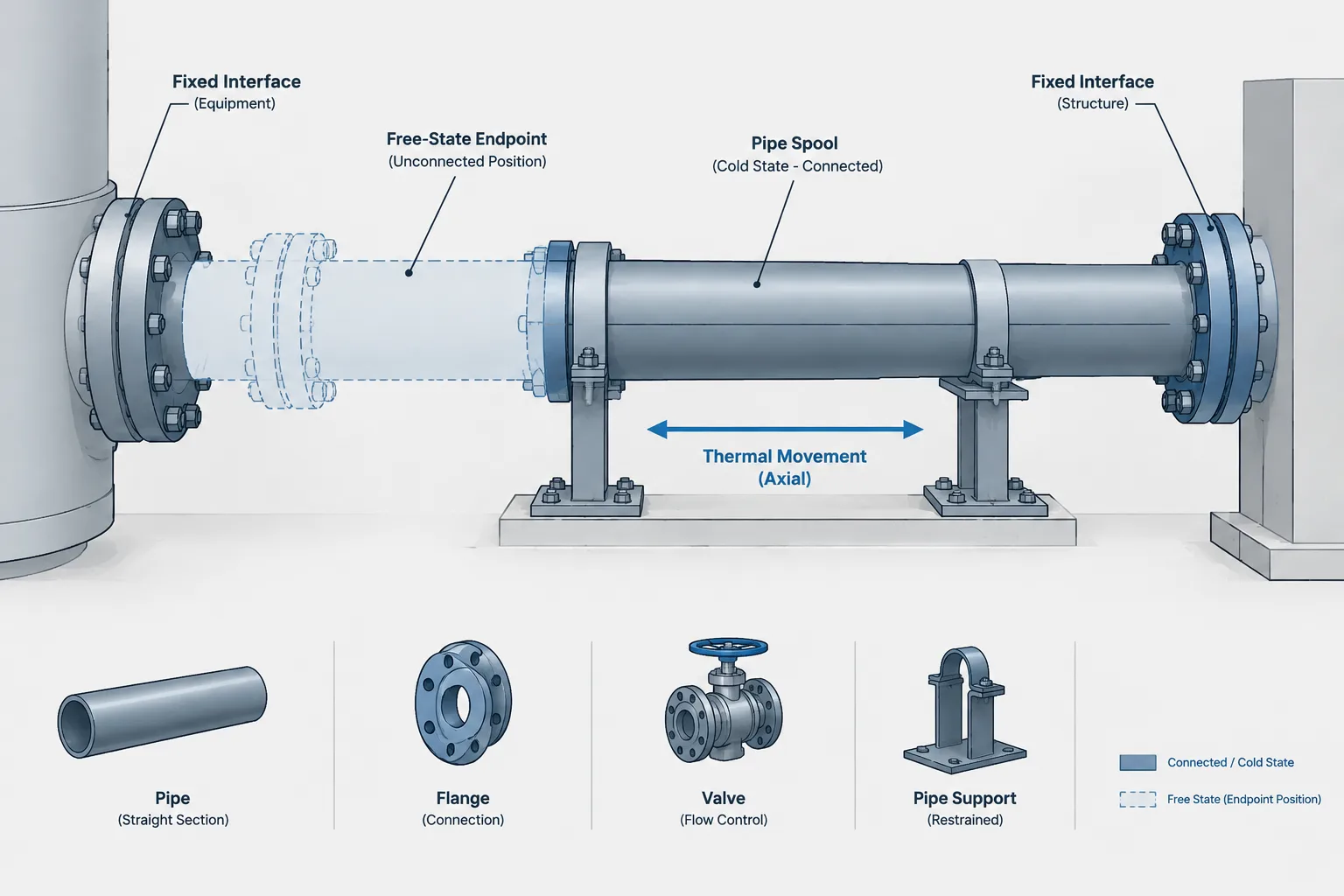
Cold spring in piping must be controlled as both an engineering requirement and a geometric-state requirement. The central drafting question is not simply where the pipe appears in the model, but whether each dimension describes the unrestrained fabricated assembly, the connected installation, or a calculated operating position.
This guide explains how to distinguish those conditions and carry the approved requirement through stress analysis, CAD, isometrics, spool fabrication, support planning, erection, and inspection. It is intended as a documentation and coordination reference; project-specific displacement instructions must come from the responsible engineering authority.
Cold spring in piping is an intentional initial displacement introduced during fabrication or installation. A pipe assembly may be made slightly shorter, longer, or differently aligned than its final connected position, then pulled or pushed into place during erection. This creates a controlled initial strain intended to influence how thermal movement, stress, and end reactions develop during operation.
The concept sounds simple, but it creates an important documentation problem: one piping system can have several valid geometric states. The fabricated free-state shape may not match the connected cold-state shape, and neither necessarily matches the displaced operating shape. A conventional CAD model often shows only one of these states.
Cold spring therefore requires coordination among piping design, stress analysis, fabrication, construction, equipment engineering, and inspection. It should never be treated as an informal instruction to force misaligned pipe into place.
What cold spring is intended to do
When piping heats or cools, it expands or contracts relative to its installed condition. Restraints, anchors, guides, equipment nozzles, and connected branches affect how that movement is distributed. Cold spring intentionally introduces part of the anticipated displacement before the system enters service.
Depending on the approved design, the initial displacement may be created by:
- Changing the free-state length of a straight run or spool.
- Offsetting an end point from its final connected location.
- Leaving a controlled gap that is closed during erection.
- Fabricating a flexible section in a preset position.
- Applying a specified movement at an anchor, equipment connection, or field joint.
The objective is generally to redistribute displacement stress or reactions between cold and operating conditions. Cold spring does not remove thermal expansion, eliminate the need for flexibility analysis, or automatically make nozzle loads acceptable. The design basis must come from the responsible stress analysis and project requirements.
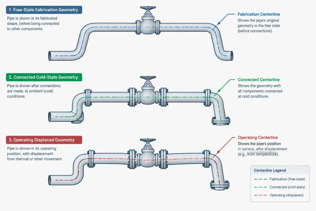
Three geometric states that must not be confused
Free-state fabrication geometry
This is the geometry of the spool or assembly before external force is applied to make the final connection. If cold spring is created by shortening a run, the free assembly will not naturally reach both connection points at the same time.
Connected cold-state geometry
This is the erected geometry after the pipe has been pulled, pushed, or otherwise moved into its specified installed position while the system is not operating. A plant model commonly represents this connected geometry because equipment nozzles, supports, and adjacent piping must appear at their installed coordinates.
Operating displaced geometry
This is the calculated position under a defined operating case. It may include thermal movement and other modeled effects. It is usually controlled in the stress-analysis model rather than represented as the primary physical arrangement in the plant CAD model.
Confusion occurs when dimensions derived from one state are applied to another. For example, measuring the connected CAD centerline and issuing that result as the unrestricted shop length could unintentionally remove the cold-spring allowance.
Cold spring is not ordinary field fit
A field-fit allowance gives construction personnel controlled material or dimensional flexibility so a spool can be trimmed after actual site conditions are verified. Cold spring is a deliberate design displacement with a specified magnitude and direction.
| Condition | Purpose | Key control |
|---|---|---|
| Cold spring | Introduce intentional initial strain | Approved displacement, location, and direction |
| Field-fit allowance | Accommodate verified site dimensions | Trim limits and field measurement |
| Construction misalignment | Unintended dimensional or positional error | Engineering disposition before forcing fit-up |
| Thermal expansion loop | Provide geometric flexibility | Loop geometry, restraints, and stress analysis |
| Preset expansion joint | Establish a manufacturer- and design-controlled initial position | Approved installation instructions and movement direction |
Calling a mismatch cold spring after fabrication does not make it an intentional design feature. Unplanned misalignment can impose unknown loads on equipment, flanges, welds, supports, and branches.
How cold spring should be represented in CAD
A single 3D model may be unable to show both the connected position and the free-state fabrication geometry without additional data. The model can still remain useful if the chosen representation is clearly defined.
A practical CAD strategy normally includes the following controls:
- Declare the modeled state. State whether the model represents the connected cold condition, free fabrication condition, or another controlled state.
- Identify the cold-spring location. Associate the requirement with a specific joint, spool, anchor, or endpoint rather than with the line generally.
- Control direction. Use coordinates, axes, or an unambiguous directional note. A magnitude without a direction is incomplete.
- Separate endpoint coordinates from free spool dimensions. Both may be needed, but they describe different conditions.
- Protect the value from automatic extraction. Review isometric dimensions, cut lists, and spool outputs so software-derived lengths do not overwrite the intentional fabrication difference.
- Connect the requirement to approved analysis data. The CAD note should not become an independent source of stress-design values.
Creating a visually disconnected model is not always the best answer. It can generate false clashes, broken connectivity, incorrect material reports, or misleading isometrics. Many projects keep the main model connected and communicate the free-state difference through controlled fabrication dimensions, installation details, or dedicated attributes.
Dimensioning and isometric documentation
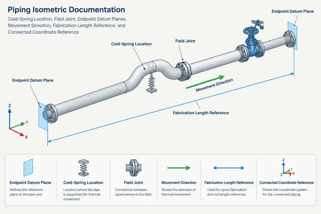
A useful cold-spring detail should allow fabrication and construction personnel to determine what is fabricated, what is moved, where the movement occurs, and what final point must be reached. Merely adding a note such as “cold pull required” leaves too much open to interpretation.
Depending on the project workflow, documentation may need to identify:
- The joint or assembly where the displacement is introduced.
- The free-state end position or spool length.
- The final connected coordinate or interface plane.
- The displacement direction and sign convention.
- The reference temperature or defined installation condition used by the design.
- Any required support, restraint, or equipment condition during fit-up.
- Hold points, inspection records, or engineering approval requirements.
Dimensions should not form a contradictory closed loop. If an overall connected dimension and a shorter free-state fabrication length are both shown without explanation, the drawing appears inconsistent. Labeling the applicable state is essential.
Supports, restraints, and equipment interfaces
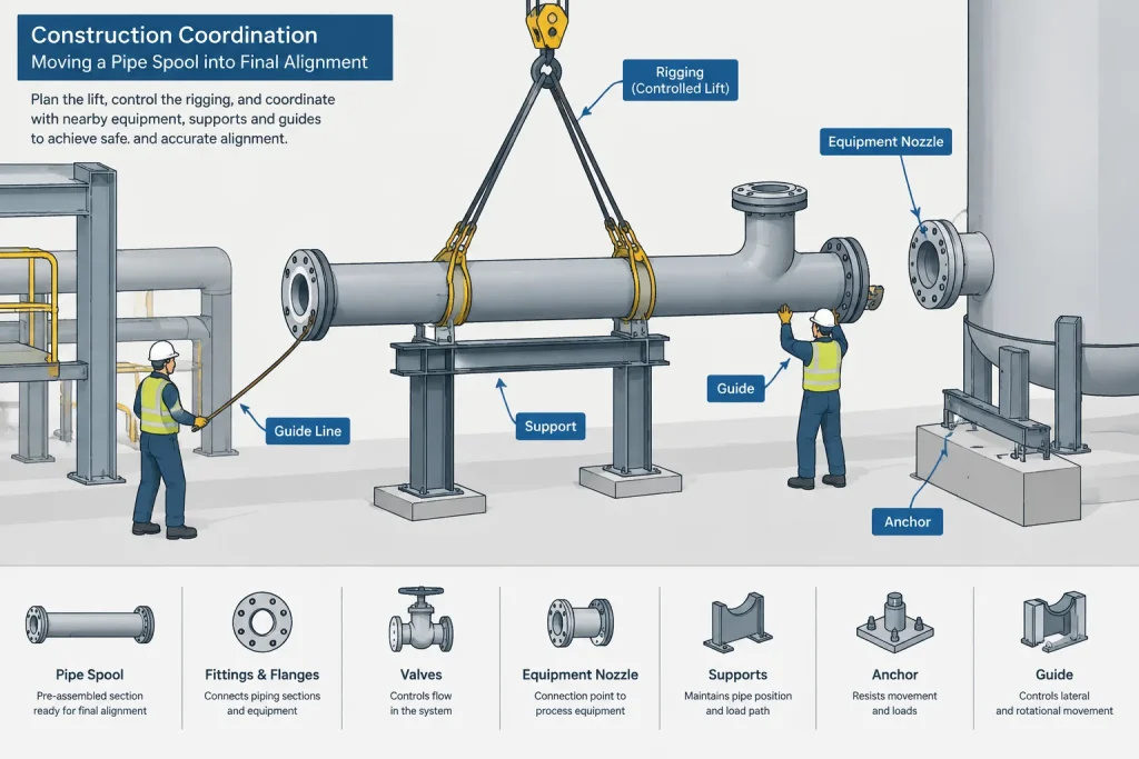
Cold spring cannot be reviewed as pipe geometry alone. The force needed to move the assembly into position may be transferred through temporary rigging, permanent restraints, equipment nozzles, or partially completed connections.
Support settings also require coordination. A guide, stop, spring support, or anchor installed in the wrong sequence can prevent the intended movement or create an unintended load path. The term cold spring should also not be confused with a variable or constant spring support; those are support devices, not the same design concept.
At rotating or static equipment, construction personnel should not use nozzle bolting as an uncontrolled pulling method. The approved erection procedure must define how alignment is achieved and which interfaces can accept installation forces.
Common CAD and construction failure modes
- Cold spring is modeled and specified twice. The geometry contains the offset, while the stress model or drawing applies it again.
- The allowance disappears during spool extraction. Shop dimensions are taken directly from the connected model.
- The direction is reversed. A sign convention differs between stress, CAD, and construction documents.
- A field-fit spool absorbs the displacement. Trimming unintentionally cancels the designed cold spring.
- Supports are fixed too early. The required installation movement becomes restrained.
- Unplanned misalignment is accepted under the same label. A fabrication error is forced into place without analysis.
- A revision changes an endpoint. The cold-spring requirement is not recalculated or reissued with the revised layout.
A coordinated review workflow
Begin with the approved stress-analysis requirement, including the affected location, movement direction, and reference condition. Decide which geometric state the plant model will represent. Then establish how the free-state fabrication information will reach the shop and field without being mistaken for normal dimensional tolerance.
Before issue, compare the stress model, 3D model, isometric, spool drawing, support arrangement, and equipment interface data. Check that the requirement appears once, remains traceable through revisions, and is not silently altered by automated dimension extraction.
Finally, treat field verification as confirmation of the engineered condition, not as permission to force any mismatch into alignment. If measured geometry, equipment position, or fabrication dimensions differ from the documented basis, the responsible engineering team should review the condition before installation proceeds.
Document-control questions before release
A cold-spring requirement is easier to audit when every participating document answers the same core questions. Before drawings or fabrication data are issued, reviewers should confirm:
- Which state is depicted? The model and drawing should identify whether their geometry is free, connected, or displaced.
- Where is the requirement applied? The controlled joint, spool, endpoint, or interface should be identifiable without relying on verbal instructions.
- What governs fabrication? Shop personnel need the approved free-state information rather than an unrestricted dimension extracted from connected model geometry.
- What governs erection? The field package should define the intended final interface and refer to the approved procedure for creating the displacement.
- How is direction interpreted? Coordinate systems, view orientation, and sign conventions must agree across stress, CAD, and construction documents.
- What happens after a revision? Changes to equipment, supports, routing, spool breaks, or connection points should trigger review of the cold-spring basis.
Verification without treating misalignment as acceptance
Inspection should establish whether the fabricated and installed conditions match the approved design information. It should not convert an unexplained mismatch into an acceptable cold-spring condition merely because the pipe can be pulled into place.
Where documents disagree, the conflict should be resolved before fit-up. A connected model coordinate, free spool dimension, stress-analysis displacement, and field measurement may each be valid, but only when their applicable geometric states and reference conditions are clearly identified.
Frequently asked questions
Is cold spring the same as forcing misaligned piping into place?
No. Cold spring is an intentional, analyzed, and documented initial displacement. Unplanned misalignment is a deviation that requires engineering review before force is applied.
Should the CAD model show the free-state or connected geometry?
Either approach can be controlled, but the modeled state must be declared. Many workflows retain connected geometry for plant coordination and communicate the free-state fabrication difference through approved dimensions, attributes, notes, or details.
Why can a model-derived spool length be wrong?
If the model represents the connected cold state, its centerline dimensions may not describe the unrestrained fabricated spool. Automatic extraction can therefore remove the intentional difference unless the cold-spring requirement is separately controlled.
Can a field-fit allowance be used to create cold spring?
Not by assumption. Field fit and cold spring serve different purposes. Any interaction between them must be explicitly resolved so trimming does not cancel or alter the engineered displacement.
Does cold spring eliminate thermal movement or flexibility analysis?
No. It changes the initial condition used to influence displacement stress or reactions. Thermal movement, restraint behavior, equipment interfaces, and piping flexibility still require appropriate analysis.
Who should authorize a change to the cold-spring requirement?
The responsible engineering team should review changes through the project’s approved process. Fabrication or construction personnel should not redefine the displacement based solely on fit-up conditions.