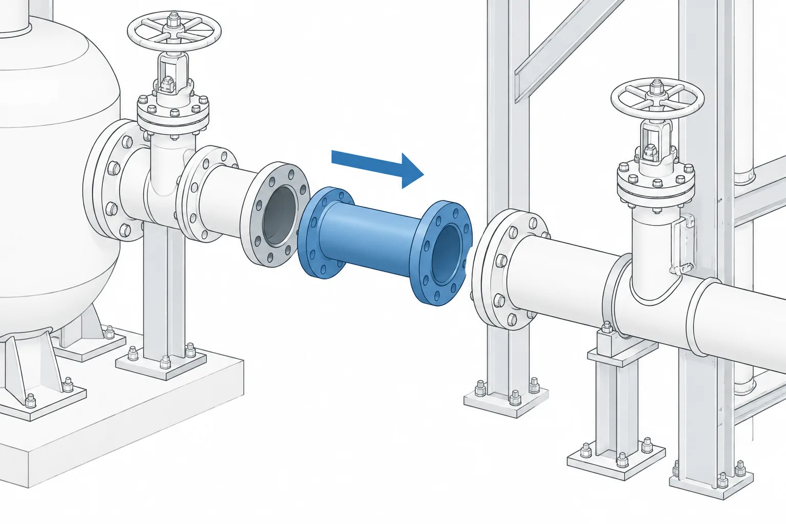
Removable pipe spools must be designed around the maintenance operation, not merely shown as separate CAD objects. The connection faces must disengage, the complete assembly must pass through a clear extraction path, and the remaining piping must stay adequately supported.
This guide explains how to coordinate break joints, movement sequences, access, handling space, attached components, and drawing information so the intended removal function remains visible throughout design and construction.
A removable pipe spool is a planned section of piping that can be disconnected and taken out without cutting the permanent system. Designers commonly use removable spools where maintenance requires access to equipment, valves, strainers, instruments, or internal components. They may also provide the temporary opening needed to install or remove a blind, clean a line, or reach equipment that cannot pass through the surrounding piping.
Representing the spool as removable is only the beginning. A workable arrangement needs suitable break joints, enough separation movement, a clear extraction path, practical handling provisions, and documentation that preserves the maintenance intent through fabrication and construction. A CAD model can show a spool that is geometrically separate yet impossible to remove in the field.
What Makes a Pipe Spool Removable?
A fabricated spool is not automatically a removable spool. Most piping is assembled from spools, but many completed sections become trapped between fixed equipment, welded connections, structures, or adjacent lines. A maintenance-removal spool is deliberately bounded by connections that can be opened and arranged so the section can be moved out of its installed position.
The intended action may involve lifting the spool vertically, sliding it horizontally, lowering it through an opening, or rotating it through a clear zone. The selected method affects joint locations, support placement, lifting access, and the space required around nearby components.
Common purposes include:
- Providing access to a pump, compressor, exchanger, vessel, or packaged-equipment nozzle.
- Allowing removal of a valve, strainer basket, flow element, or inline instrument.
- Creating space for maintenance tools or inspection equipment.
- Providing a planned location for temporary isolation or cleaning work.
- Avoiding field cutting during recurring maintenance.
- Separating piping from equipment before the equipment is moved.
Choose Break Joints Around the Maintenance Task
The break joints define the limits of the removable assembly. Flanged joints are often used because they can be unbolted, but other demountable connection types may be appropriate when allowed by the project piping specification and equipment requirements. Connection selection must come from the applicable design documents rather than from the convenience of the CAD layout alone.
Place each break joint where workers can reach the fasteners, separate the joint, and control the released spool. A flange hidden against structural steel may be visible in the model but inaccessible to tools. Similarly, a joint placed directly above equipment can create a handling problem if the spool has no supported position after its bolts are removed.
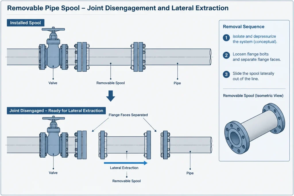
When selecting spool limits, review:
- Which component must remain in place and which item must move.
- Whether the disconnected piping can tolerate temporary movement.
- Access to bolts, couplings, clamps, or other joint hardware.
- Gasket removal and replacement access.
- The weight and center of gravity of the complete removable assembly.
- Branches, vents, drains, tubing, heat tracing, insulation, and instruments attached to the spool.
- Support conditions before, during, and after removal.
Flange Separation Is Different from Spool Extraction
Two distinct movements must be checked. First, the joint faces need enough relative movement to disengage without damaging sealing surfaces or adjacent equipment. Second, the entire spool needs a path out of the surrounding layout.
A spool bounded by two rigid flanges can be trapped even when open space exists beside it. If neither connected system can move, the spool may not clear flange hubs, raised faces, alignment features, or protruding ends. Forcing the piping apart in the field is not a reliable substitute for planned removal geometry.
Possible layout strategies include locating the spool where one side has controlled flexibility, using an arrangement that can move in more than one direction, or dividing a long trapped section into smaller removable pieces. The appropriate solution depends on the piping system, joint type, allowable movement, and maintenance procedure. An expansion joint or flexible connector should not be introduced merely as a geometric shortcut; such components have separate pressure, movement, restraint, and specification implications.
Model the Extraction Path, Not Just the Installed Position
The installed model represents only one stage of the maintenance operation. A useful CAD review also considers intermediate positions between installed and fully removed. During extraction, elbows, branches, flanges, valve operators, and lifting attachments may sweep through space that appears clear when only the final position is shown.
For important or congested areas, create a temporary copy of the spool and move it through the proposed sequence. Use a simplified envelope if detailed component geometry makes the review difficult. The goal is to find collisions with steel, cable trays, platforms, handrails, equipment, insulation, other piping, and building elements.
Typical extraction directions
| Removal method | Primary CAD checks | Common constraint |
|---|---|---|
| Vertical lift | Overhead clearance, lifting route, branch projections, upper-level openings | Steel, platforms, cable trays, or piping above |
| Horizontal slide | Joint separation, support interference, side clearance, landing area | Adjacent lines or fixed equipment |
| Vertical lowering | Clear opening below, lower-level access, load control, temporary support | Grating, floor penetrations, or equipment underneath |
| Rotation and withdrawal | Swept envelope, center of gravity, connection projections, operator clearance | Corners that trap elbows or branches |
Do not assume that a surrounding clearance box proves removability. A box can identify nearby obstructions, but it does not show the actual sequence or rotational sweep of an irregular spool.
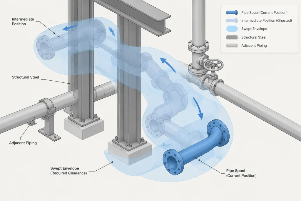
Account for the Full Assembly Envelope
Centerline geometry is insufficient for a removal study. Include the outside envelope of flanges, bolts where relevant to access, fittings, valve bodies, operators, branch connections, drains, and other projections. Insulation and removable insulation covers may also control the available space.
Confirm whether insulation is intended to remain on the spool during removal. If it must be stripped first, the drawings or maintenance documentation should make that assumption clear. The same applies to detachable items such as tubing, instruments, heat-tracing leads, grounding connections, and small-bore vents or drains.
Valve operators deserve particular attention. A small pipe spool containing a geared valve can have a much larger extraction envelope than its pipe size suggests. The operator may also shift the assembly’s center of gravity away from the pipe centerline.
Supports and Temporary Stability
Removing a spool changes the load path. Supports attached to the spool leave with it, while nearby supports may be asked to hold piping that was previously stabilized by the connected assembly. CAD coordination should identify which supports belong to the removable section and which remain with the permanent system.
Review whether the remaining pipe ends will be stable after disconnection. A nearby guide, spring support, hanger, or equipment nozzle may not be intended to resist loads created by maintenance handling. These questions may require input from piping stress, structural, equipment, and maintenance disciplines.
A maintenance concept may also need a temporary support or landing location. If a spool must be held while the final bolts are removed, show or describe how that operation is expected to occur rather than leaving the assembly suspended without an obvious handling method.
Lifting and Handling Information
CAD should communicate the handling concept without inventing lifting details. Permanent lifting lugs, temporary rigging points, monorails, davits, cranes, or portable lifting equipment require project-specific engineering and verification. Their capacity and suitability cannot be established from visual model clearance alone.
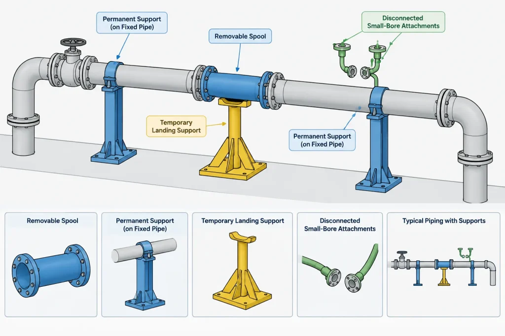
Still, the layout team can identify the intended lift direction, likely handling zone, overhead obstructions, and possible equipment setup areas. Approximate component weight data used for planning should be traceable to controlled material or vendor information and should distinguish the complete removable assembly from the pipe-only weight.
How to Document a Removable Spool
The model, isometric, general arrangement, and maintenance drawing should communicate the same limits. A note saying “removable” is useful only when readers can determine exactly which joints define the item.
Documentation may include:
- A unique spool or removable-assembly identifier.
- Clearly identified break joints.
- The intended removal direction or sequence.
- Items that must be disconnected before movement.
- References to related equipment or maintenance requirements.
- Identification of field welds or closures that would prevent routine removal.
- Temporary-support or handling notes where these have been engineered.
- A defined clearance or reserved maintenance zone on arrangement drawings.
A fabrication spool number and a maintenance-removal identifier do not always serve the same purpose. One controls fabrication and erection, while the other explains an operational maintenance boundary. If the project uses both, their relationship should be unambiguous.
Common CAD Review Failures
- Checking only the final removed location: The spool collides with an obstruction during the movement sequence.
- Ignoring joint disengagement: There is no movement available to separate two rigid end connections.
- Using pipe centerlines as the clearance basis: Flanges, branches, insulation, and operators occupy the proposed path.
- Leaving attached services out of the model: Tubing, tracing, drains, or instruments prevent removal.
- Placing supports across the removal boundary: The spool cannot move without dismantling an unplanned support assembly.
- Providing inaccessible break joints: Workers cannot reach fasteners or sealing surfaces.
- Assuming field flexibility: Construction or maintenance personnel are expected to force connected piping aside.
- Failing to reserve the route: A later discipline places steel, tray, or equipment inside the extraction zone.
A Practical Review Workflow
- Define the maintenance task and identify the item that must be removed or accessed.
- Establish the proposed spool limits using connections permitted by the piping specification.
- Model the complete assembly envelope, including projections and attached items.
- Check how each break joint will be opened and disengaged.
- Move a temporary spool copy through the intended extraction sequence.
- Review permanent and temporary support conditions.
- Coordinate the handling route with structure, equipment, electrical, and other piping.
- Record the boundary, removal direction, assumptions, and required disconnections on controlled deliverables.
- Recheck the maintenance zone after significant model changes.
Design Removability as a Controlled Function
A successful removable spool is more than a pair of flanges around a convenient length of pipe. It is a coordinated maintenance feature involving connections, movement, access, support, handling, and documentation. CAD provides an effective way to test this function, but only when the review includes the full extraction sequence rather than the installed geometry alone.
Final connection details, loads, lifting provisions, dimensions, and clearances should be verified against the project piping specification, approved equipment information, structural design, maintenance plan, and applicable engineering requirements. Treat the removable-spool boundary as design intent that must remain visible as the model and drawings develop.
Maintenance Clearance Versus Normal Layout Clearance
Normal layout clearance keeps installed components from interfering with surrounding objects. Maintenance clearance serves a different purpose: it reserves the space needed to disconnect, move, rotate, support, and handle an assembly. A spool can satisfy ordinary model-clearance checks while still being trapped during removal.
The maintenance envelope should therefore reflect the actual sequence rather than a generic open space around the installed pipe. It may need to include tool access, joint separation, projecting branches, valve operators, insulation assumptions, temporary support positions, and the swept path between installed and removed locations.
Keep Removal Assumptions Visible
Removability can be lost when another discipline adds steel, cable tray, equipment, or piping inside an unmarked route. It can also be lost when a support is revised, an operator orientation changes, or an attached service is added late in design.
Useful model and drawing information should make the maintenance boundary understandable without relying on informal project knowledge. Clearly identify the spool limits, intended direction of movement, required preliminary disconnections, and any reserved handling area. If insulation or attached items must be removed first, record that assumption in the controlled documentation.
Questions for a Coordinated Model Review
- Can workers reach and operate the hardware at every break joint?
- Can the connection faces separate without forcing fixed piping or equipment?
- Does the modeled path include intermediate positions and rotational sweep?
- Are operators, branches, insulation, tubing, drains, tracing, and instruments represented?
- What supports leave with the spool, and what supports remain?
- Are the disconnected pipe ends stable throughout the maintenance operation?
- Is there a controlled place to support or land the assembly during handling?
- Is the extraction route protected from later model changes?
These checks support coordination but do not replace project-specific review of connection design, loads, lifting provisions, structural capacity, equipment requirements, or maintenance procedures.
Frequently Asked Questions
Is every fabricated pipe spool removable?
No. Fabrication spools are assembly units, but they may become trapped by welded connections, fixed equipment, structures, supports, or adjacent piping. A maintenance-removal spool requires deliberate break joints and a workable movement path.
Why are flanges alone not enough to make a spool removable?
Flanges provide demountable joints, but the faces still need room to disengage. The spool must then clear flange projections, fittings, branches, supports, insulation, and surrounding objects during the full extraction sequence.
What should be included in the CAD removal envelope?
Include the complete assembly geometry and relevant projections, such as flanges, fittings, operators, branches, attached services, and insulation that remains during removal. Intermediate and rotated positions should also be reviewed.
Should the extraction path be modeled?
For congested or maintenance-critical arrangements, moving a temporary copy or simplified envelope through the proposed sequence can reveal collisions that are invisible in the installed position.
How should a removable spool be identified on drawings?
Documentation should clearly show the assembly boundary and break joints. It may also identify the removal direction, required disconnections, maintenance zone, support assumptions, and relationship between the fabrication spool designation and the maintenance-removal identifier.
Who should review the removal concept?
The required review depends on the project, but piping layout, maintenance, equipment, structural, piping stress, and other affected disciplines may need to confirm access, stability, handling, and surrounding clearances.