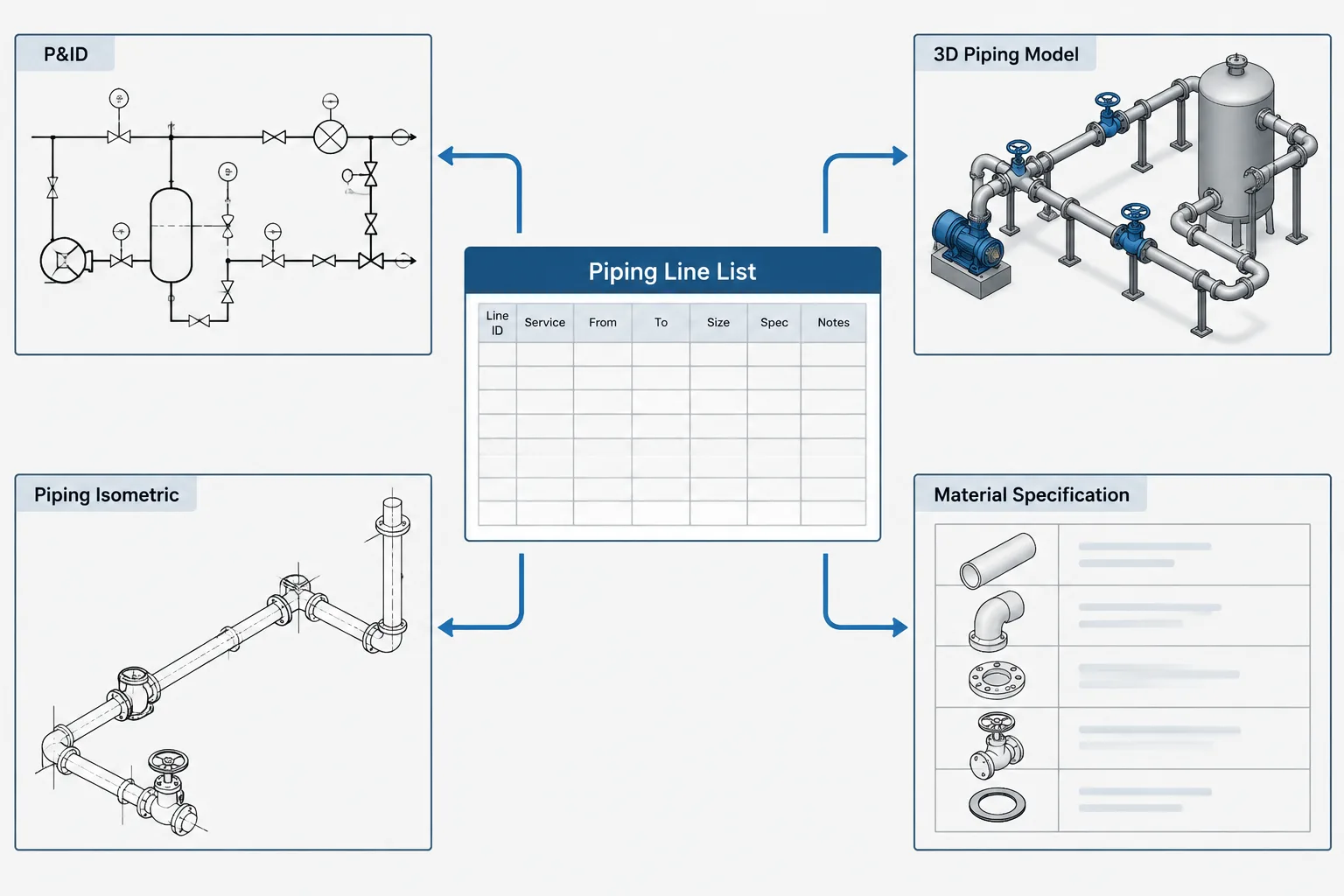
A piping line list sits at the center of several engineering workflows, but it is not a substitute for the documents and systems that define process intent, material selection, physical routing, or fabrication details. Effective coordination requires users to understand what each deliverable communicates, where each data field originates, and how approved changes move between systems.
This guide explains how to compare a piping line list with the P&ID, piping specification, CAD model, and isometric without assuming that any single deliverable governs every type of information. It also provides a practical framework for investigating mismatches, controlling revisions, and preventing drawing annotations from drifting away from underlying engineering data.
A piping line list is a structured register of process and utility lines in a project or facility. It brings important line-level information into one place so engineers, designers, drafters, analysts, fabricators, and operators can work from a coordinated data set.
The line list does not replace the P&ID, piping material specification, CAD model, or isometric drawing. Each document has a different purpose. Problems arise when users assume that identical-looking fields have the same authority everywhere, or when a change is entered in one deliverable but not propagated to the others.
A reliable workflow therefore depends on two things: clearly assigned data ownership and repeatable cross-checks between documents.
What a piping line list is intended to do
The line list organizes information by line number or another approved line identifier. Depending on project practices, it may include nominal pipe size, service description, piping class, design conditions, operating conditions, insulation requirements, tracing requirements, test information, source and destination, and other line-specific attributes.
Not every organization uses the same columns. A line list should reflect the project’s engineering procedures rather than an assumed universal template. Some fields may also be maintained in a database and merely exported into a spreadsheet or report.
The line list is especially useful for:
- reviewing many lines without opening individual drawings;
- sorting lines by service, size, material class, insulation, or other attributes;
- supporting piping, process, stress, materials, estimating, and construction activities;
- identifying missing, duplicated, or inconsistent line identifiers;
- tracking line-level changes through project revisions; and
- providing structured input to CAD and plant-design databases.
It is best treated as a controlled engineering deliverable, not as an informal index assembled after the design is complete.
How the line list differs from related deliverables
| Deliverable | Primary purpose | Typical piping information | Important limitation |
|---|---|---|---|
| P&ID | Communicate process intent and functional relationships | Line identifiers, equipment connections, valves, instruments, branches, flow relationships, and specification breaks | Usually does not define physical routing or fabrication geometry |
| Piping line list | Maintain structured line-level engineering data | Service, size, class, conditions, insulation, tracing, testing, and related attributes as required by the project | Does not show the complete physical arrangement of components |
| Piping specification | Define permitted materials and components for a piping class | Pipe, fittings, flanges, valves, branch connections, gaskets, bolting, and applicable selection rules | Does not identify where every line is routed |
| CAD or plant model | Represent physical layout and component connectivity | Routes, component sizes, ports, elevations, coordinates, orientations, and model properties | Displayed geometry may not contain every engineering condition or requirement |
| Piping isometric | Communicate spool geometry, fabrication, and installation information | Dimensions, components, welds, supports, line identity, elevations, and material references | Represents a particular extracted or drafted configuration and may lag behind current model data if controls are weak |
The exact authority of each deliverable must be stated in the project execution plan, engineering procedures, or document responsibility matrix. There is no safe general rule that one document automatically overrides all others.
Line number consistency is necessary but not sufficient
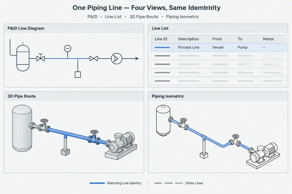
A matching line number does not prove that records describe the same engineering state. The size, piping class, service, insulation, or endpoint data may still differ. Conversely, a deliberate line-number change may indicate a real design boundary rather than a clerical inconsistency.
When checking line identity, review both the identifier and the context around it:
- Does the line connect the same source and destination?
- Is the nominal size consistent at the relevant segment?
- Does the piping class match the applicable material selection?
- Are specification breaks located at the intended physical component or joint?
- Do service and flow descriptions agree with the P&ID?
- Have branches inherited the correct identifier and properties?
- Are insulation and tracing attributes assigned to the correct extent?
This distinction is important in CAD databases. A graphical label can look correct even when the underlying object properties are stale. Checks should query the component and pipeline data, not only the annotation visible on a drawing.
Data ownership should be defined by field
Assigning ownership only at the document level can be too vague. A more useful approach assigns responsibility by data field. Process engineering may originate some conditions and service descriptions, while piping materials engineering controls class definitions. The piping design team may maintain model connectivity, route geometry, insulation representation, or drawing annotations. Other disciplines may own separate attributes.
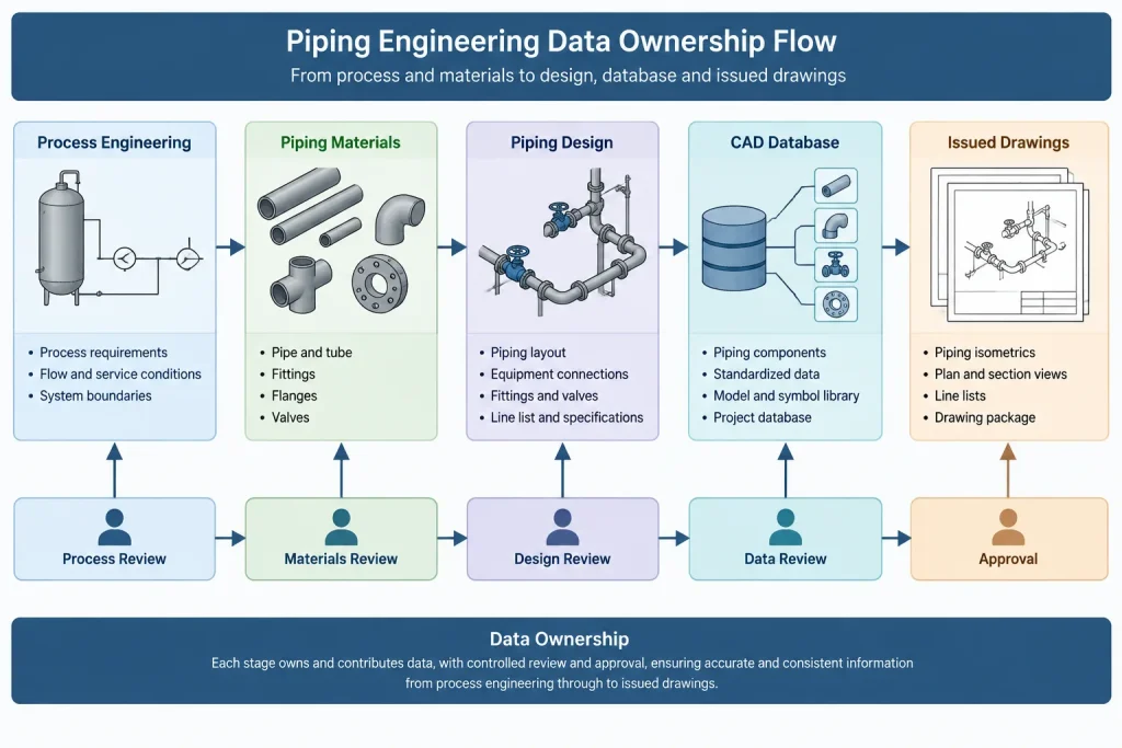
Field ownership does not mean that only one discipline may view or question the value. It identifies who is authorized to establish or approve the governing information. It also provides a clear destination for discrepancy reports.
Questions for a data-responsibility matrix
- Who originates each field?
- Who reviews and approves it?
- Which system stores the governing value?
- Which deliverables receive copies or synchronized values?
- How is a change requested and authorized?
- What event triggers regeneration of drawings or reports?
- How are superseded values retained for revision history?
Without these decisions, teams may correct the same conflict differently in separate files.
Common line-list coordination problems
Size changes without a controlled line-segment decision
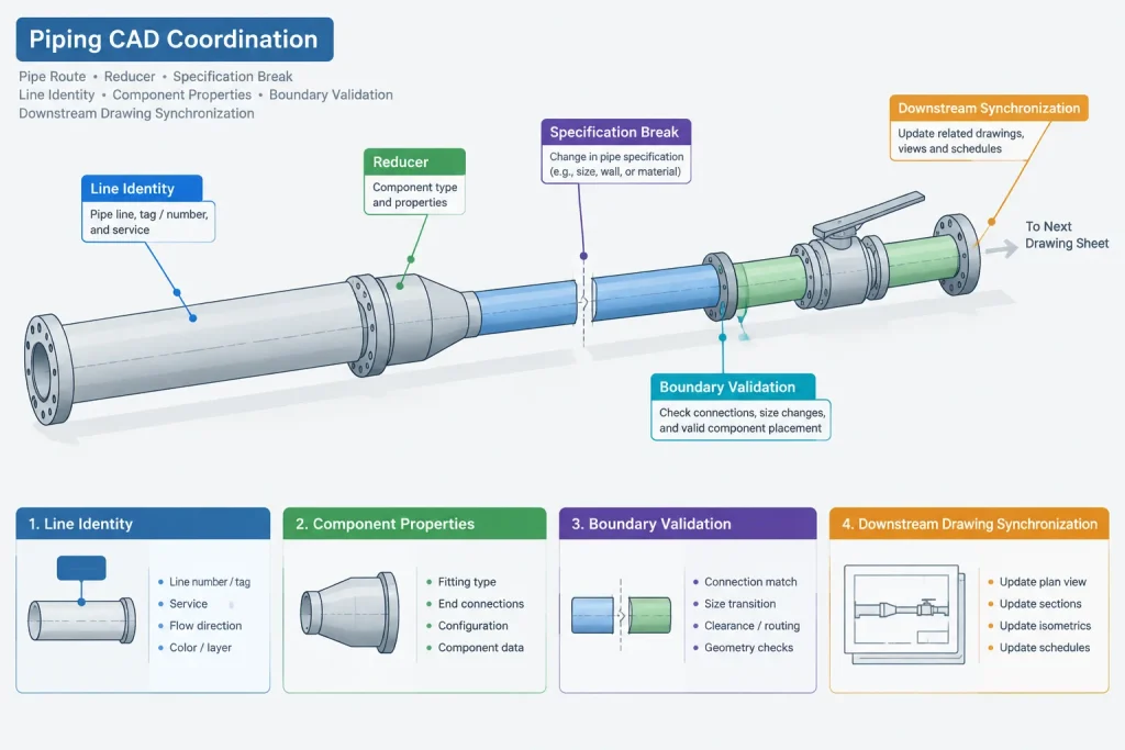
A reducer does not automatically answer whether the downstream segment retains the same line number. That decision depends on the project’s line-numbering rules and process-document conventions. The P&ID, line list, model, and isometric must apply the chosen rule consistently.
Piping-class changes entered as text only
Changing a class label on a drawing does not necessarily update the modeled components. Existing fittings, valves, flanges, gaskets, or branch components may remain assigned to the previous class. A class change requires a component-level validation, not just an annotation edit.
Line records created before routing is mature
Early line lists may include provisional endpoints, sizes, or services. These are useful for design development, but provisional status must be visible. Otherwise, downstream users may treat preliminary information as released design data.
Deleted lines that remain active elsewhere
A line removed from a P&ID may remain in the CAD model, line list, stress model, or isometric register. Deletion should be handled as a controlled change with impact review. Simply erasing a row can remove the history needed to understand related documents.
Multiple records for one continuous line
Duplicate records may result from spelling differences, inconsistent punctuation, imported data, or separately modeled areas. Automated normalization can help find these cases, but it should not merge records until engineering intent and connectivity have been checked.
A practical line-data cross-check workflow
- Establish the comparison baseline. Record the revisions or issue states of the P&ID set, line list, model database, piping specifications, and extracted drawings.
- Normalize identifiers for comparison. Account for approved formatting differences while preserving meaningful size, service, class, sequence, and area fields.
- Compare line existence. Identify lines present in one controlled source but absent from another.
- Compare key attributes. Review size, class, service, insulation, tracing, conditions, and endpoints where those fields are applicable.
- Check physical connectivity. Confirm that modeled segments connect to the intended equipment nozzles, branches, valves, and continuation points.
- Review boundaries. Examine reducers, specification breaks, equipment connections, battery limits, tie-ins, and interfaces between model areas.
- Classify discrepancies. Separate engineering changes, drafting errors, database synchronization failures, and acceptable document-purpose differences.
- Correct the governing source first. Apply an approved change where the field is owned, then synchronize dependent deliverables.
- Regenerate and recheck outputs. Updated isometrics or reports should be compared again rather than assumed correct.
- Close the issue with traceability. Record who resolved the discrepancy, what changed, and which deliverables were updated.
Using the line list in a CAD workflow
Where software and project procedures permit, line data should be transferred through controlled database mappings rather than repeated manual entry. Dropdowns, validated class references, and governed service descriptions can reduce typographical variation. They do not eliminate the need for engineering review.
Model properties should also be separated into line-level and component-level data. A line may carry a service and class, while an individual valve has its own tag, end connection, operator orientation, and procurement identity. Copying every property to every object can create conflicting duplicates unless inheritance and override rules are understood.
Before issuing isometrics, the design team should confirm that annotations are generated from current model properties and that intentional overrides are documented. An untracked text override may conceal incorrect source data and reappear as a conflict at the next extraction.
Treat discrepancies as controlled engineering questions
When the line list, P&ID, CAD model, and isometric disagree, the safest response is not to choose whichever value seems most plausible. First identify the field owner, the current approved revision, and whether the difference reflects process intent, material selection, layout development, or an outdated deliverable.
A well-managed piping line list becomes more than a spreadsheet. It acts as a structured coordination layer connecting process definition, material requirements, physical layout, fabrication drawings, and project change control. Its value depends less on the number of columns than on clear ownership, synchronized data, and disciplined verification.
How to apply this guide during a design review
Begin by defining the purpose of the review. A line-existence check, an attribute comparison, a model-connectivity review, and an isometric verification answer different questions. Combining them without a clear scope can produce a long discrepancy report that mixes genuine engineering conflicts with acceptable differences in document purpose.
Record evidence before proposing a correction
For each discrepancy, capture the affected line identifier, compared deliverables, revision status, conflicting fields, and relevant physical or process context. This gives the field owner enough information to evaluate the issue without relying on screenshots or isolated annotations.
A useful discrepancy record should distinguish among:
- engineering intent conflicts, where controlled sources describe different requirements;
- model-data conflicts, where object properties do not match approved line information;
- drawing-output conflicts, where an annotation or extracted view does not reflect its source data;
- revision conflicts, where deliverables represent different approved states; and
- presentation differences, where the information varies because the documents serve different purposes.
Verify the correction across dependent outputs
Closing a discrepancy requires more than editing the document where it was discovered. The governing source should be corrected through the approved process, dependent data should be synchronized, and affected outputs should be regenerated or revised as required. The reviewer should then confirm that the correction did not create a new inconsistency at a branch, specification boundary, equipment connection, or continuation point.
Line-list checks at project transitions
Line-data reviews are especially valuable when responsibility or design status changes. Examples include moving from process development into detailed piping design, transferring model areas between teams, preparing fabrication outputs, and assembling facility records for operations.
At each transition, confirm that provisional fields are identifiable, deleted lines remain traceable, approved changes have reached downstream deliverables, and intentional overrides are documented. This helps the receiving team distinguish unresolved design work from valid project-specific exceptions.
Practical review principle
Do not resolve a conflict by selecting the value that appears most detailed or most recently edited. Determine who owns the field, which approved issue applies, and whether the compared records describe the same line segment and design state. That approach turns document comparison into controlled engineering verification rather than informal reconciliation.
Frequently asked questions
Is the piping line list the master source for all line data?
Not necessarily. A line list may be the governing location for selected attributes while other fields are controlled by process engineering, piping materials, the plant database, or another approved system. Authority should be assigned by field in the project procedures.
Should a P&ID and an isometric contain identical information?
No. They should agree on applicable shared information, but they serve different purposes. The P&ID communicates process intent and functional relationships, while the isometric communicates a particular piping configuration for fabrication or installation. Differences are acceptable when they reflect document purpose rather than conflicting engineering states.
Why can a CAD label be correct while the model data is wrong?
A label may be manually entered, overridden, or left unchanged after object properties are edited. Reviewers should inspect the underlying pipeline and component records instead of relying only on visible drawing text.
Does a reducer always require a new line number?
No universal rule applies. The decision depends on the approved line-numbering convention and how the project defines line segments. The chosen convention must be applied consistently across the P&ID, line list, model, and extracted drawings.
How should deleted piping lines be handled?
Deletion should follow controlled change procedures. Related model objects, drawings, analysis records, reports, and registers should be reviewed, while enough revision history is retained to explain the change.
What should happen when the line list and model disagree?
Identify the conflicting field, confirm the applicable revisions, locate the field owner, and determine whether the difference is an approved design change or an outdated record. Correct the governing source first, then update and verify dependent deliverables.