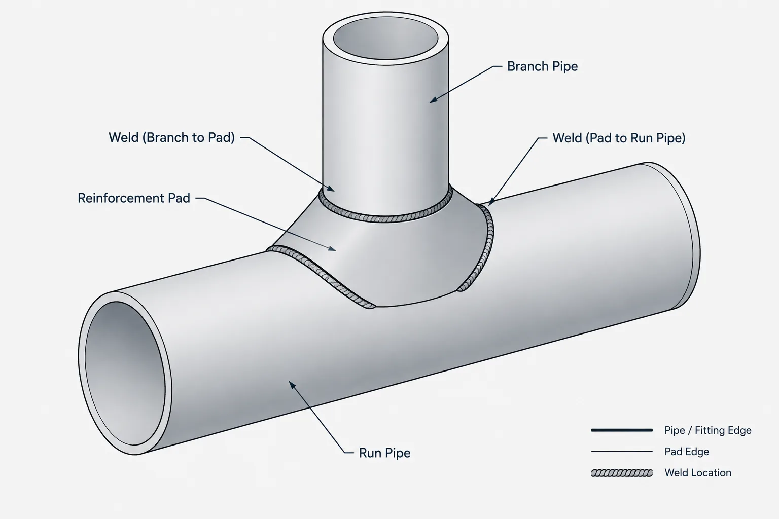
Branch reinforcement pads in piping CAD require more than placing a ring-shaped solid around a branch. The representation must preserve the relationship among the run pipe, branch neck, pad contour, weld documentation, material data, and any controlled fabrication details.
This reference explains what designers and drafters should communicate without treating the CAD model as proof of structural adequacy. Use it to review model geometry, component identity, drawing callouts, material reporting, and coordination with the approved branch design.
A branch connection removes material from the wall of a run pipe and introduces localized loads around the opening. Depending on the piping design, the required reinforcement may come from the run and branch walls, a purpose-made branch fitting, an integrally reinforced outlet, or a separate reinforcing pad. The visible pad is therefore only one possible part of the reinforcement strategy.
For a CAD designer, the main task is not to determine whether a branch is structurally adequate. That decision belongs to the applicable design calculation and project specification. The CAD model and drawings must instead represent the selected branch arrangement accurately enough for layout, material control, fabrication, examination, insulation, and maintenance planning.
What Is a Branch Reinforcement Pad?
A branch reinforcement pad, often called a repad, is a separate piece of material fitted around a branch opening and welded to the run pipe and branch neck. Its purpose is to add reinforcing area in the region affected by the opening. A typical pad follows the curvature of the run pipe and has an opening shaped to fit around the branch.
The pad should not be treated as a generic washer added whenever a branch looks weak. Whether it is needed, and what geometry and material it requires, depends on the governing design basis. The adequacy of the connection may involve pressure design, external loads, cyclic service, material compatibility, fabrication method, and other project-specific considerations.
Terminology varies among companies and fabricators. Drawings may use terms such as reinforcing pad, reinforcement pad, repad, or RF pad. The abbreviation RF can also mean raised face in flange documentation, so the intended meaning should be clear from context or stated explicitly.
Repad, Wear Pad, and Branch Outlet Fitting Are Not the Same
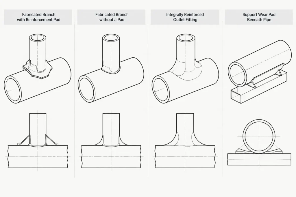
Several piping components can look similar in a simplified model. Their functions and documentation are different.
| Item | Primary function | Typical CAD distinction |
|---|---|---|
| Branch reinforcement pad | Adds material around a branch opening as part of the designed reinforcement arrangement | Surrounds the branch neck and conforms to the run pipe |
| Wear pad or wear plate | Protects the pipe surface or spreads contact at a support | Located at a support interface rather than around a process opening |
| Integrally reinforced outlet | Provides a branch connection with reinforcement incorporated into the fitting body | Modeled and listed as a distinct outlet fitting, not as a separate loose pad |
| Fabricated branch without a pad | Uses available reinforcement from the run, branch, or another qualified detail | Shows the branch intersection and weld detail without an added pad component |
| Local attachment pad | Provides an attachment or load-distribution surface for a support or structural item | Associated with the attachment location and support detail |
Calling every curved plate a repad can create material takeoff errors and may obscure the design function. Component descriptions, model properties, and drawing callouts should distinguish reinforcement from support protection and other attachments.
Geometry That the CAD Model Should Communicate
Run and branch relationship
The model should establish the run size, branch size, branch centerline, and branch orientation. A branch that is normal to the run produces a different intersection from an angled or lateral connection. Do not scale a standard pad symbol and assume that it represents the resulting saddle geometry.
Pad extent and contour
A fabricated pad conforms to the run pipe surface. Its projected plan shape may appear circular, oval, or otherwise modified depending on the viewing direction and connection geometry. A simple flat ring may be adequate for a schematic representation, but fabrication-level geometry should be based on the approved detail or developed pattern.
The model must also distinguish the pad outside boundary from the branch opening. Confusing these edges can affect clash reviews, weld access assessment, insulation details, and shop interpretation.
Pad thickness and pipe surface
Pad thickness contributes to the external envelope of the assembly. Even when the thickness is visually small, it can matter near adjacent branches, supports, insulation, tracing, or tightly packed equipment connections. It should come from controlled design information rather than graphical proportion.
A nominal CAD cylinder usually represents an ideal outside diameter. It does not show pipe ovality, weld profile, forming variation, or the fit-up gap that a fabricator may encounter. The model should therefore communicate design geometry without implying perfect physical contact everywhere.
Branch projection
Adding a pad does not automatically define the branch projection. The branch neck length, run centerline relationship, fitting takeout, weld preparation, and connection endpoint must be controlled independently. A pad should not accidentally shift a flange face or another required branch endpoint when components are replaced or updated.
Welds and Vent Openings
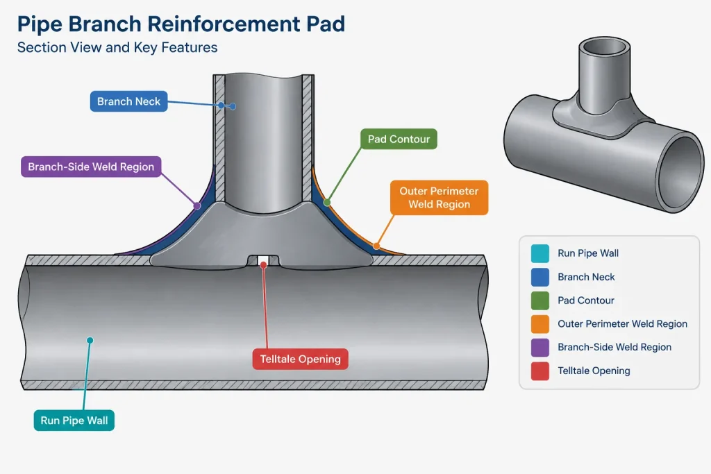
A reinforcement pad commonly involves welds at its outer perimeter and around the branch neck, but the exact joint arrangement must follow the approved fabrication detail. A generic model should not be used to infer weld type, size, examination, or acceptance criteria.
Some reinforcement-pad details include a vent or telltale opening. Such an opening can provide communication with the space beneath the pad during fabrication activities and may assist with leak indication, depending on the specified procedure. Its presence, location, treatment, and final condition are controlled details; they should not be added or omitted merely because a CAD library component includes one.
When the opening must be documented, identify it using the project’s approved terminology. Avoid modeling it as an unexplained process connection. It normally does not represent a branch that should receive a valve, plug, or line number unless the governing detail specifically says otherwise.
Material and Specification Control
A pad that looks correct geometrically may still be incorrect as a piping component. Material selection must be compatible with the approved branch design, run pipe, welding requirements, service conditions, and piping specification. Designers should not populate a material field by copying the run pipe description without confirmation.
Useful controlled attributes may include:
- Line number or parent pipeline reference
- Run and branch nominal sizes
- Component description or pad identifier
- Material designation
- Thickness or approved detail reference
- Branch orientation
- Fabrication or weld-detail reference
- Vent or telltale opening requirement, when applicable
- Design-calculation or engineering-reference status
Not every attribute belongs in visible drawing text. The objective is to keep the model, isometric, material list, branch table, and calculation reference coordinated without crowding the deliverable.
Choosing the Right Modeling Detail
The appropriate representation depends on how the model will be used.
- Schematic or early layout: A tagged symbolic pad may be sufficient if its envelope and status are clear.
- General arrangement model: Show enough external geometry to support spacing, access, insulation, and interference reviews.
- Fabrication model: Use the approved contour, thickness, opening, branch projection, and detail references required by the fabrication workflow.
- Analysis handoff: Confirm what the analyst needs. A visible pad solid does not automatically create the correct branch flexibility or stress-analysis representation.
Excess detail can be as misleading as insufficient detail. A highly realistic weld bead or cutout may appear fabrication-ready even when its dimensions are only placeholders. Model status and data maturity should remain visible to reviewers.
Common CAD and Documentation Errors
- Adding a pad by habit: Similar-looking branches may have different reinforcement solutions.
- Using the pad to hide a poor intersection: The run opening and branch fit-up still need valid geometry.
- Listing an integral outlet and a separate pad: This can duplicate reinforcement components in the bill of material.
- Confusing a repad with a support wear pad: The material purpose and documentation path are different.
- Leaving the pad untagged: An unclassified solid can disappear from material reports or be mistaken for insulation.
- Assuming the CAD block proves compliance: Geometric resemblance is not a branch reinforcement calculation.
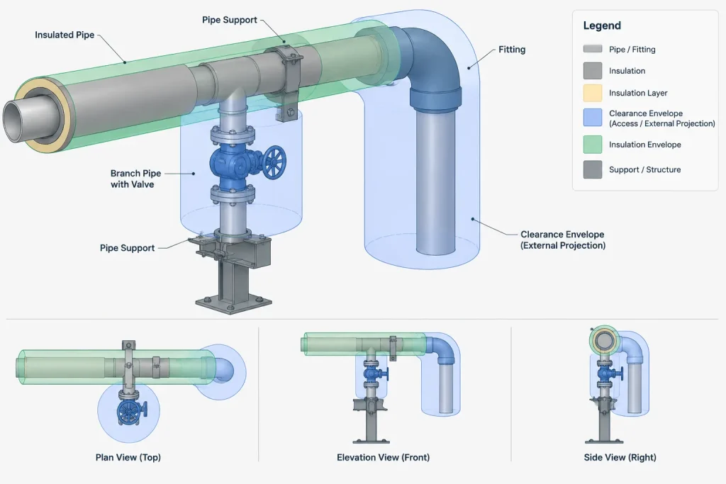
- Ignoring insulation and tracing: The local projection may require a modified insulation envelope or installation detail.
- Inventing a vent treatment: Vent location and final handling must come from approved requirements.
A Practical Review Workflow
- Confirm the branch type. Determine whether the connection is fabricated, fitting-based, or integrally reinforced.
- Locate the controlling information. Check the piping specification, branch table, engineering calculation, approved detail, or vendor data as applicable.
- Verify geometry. Review run and branch sizes, centerlines, orientation, opening, pad contour, thickness, and branch projection.
- Check component identity. Make sure the model description distinguishes the repad from wear plates, attachments, and outlet fittings.
- Coordinate weld documentation. Reference the approved weld or fabrication detail instead of deriving requirements from model appearance.
- Review nearby space. Check adjacent welds, fittings, supports, insulation, tracing, and examination access.
- Reconcile deliverables. Compare the 3D model, isometric, branch schedule, bill of material, and engineering records.
The Key Principle
A branch reinforcement pad is a designed part of a connection, not decorative CAD geometry. The model should show what has been selected, preserve its relationship to the run and branch, and carry enough data to connect engineering intent with fabrication documentation. Its presence alone does not establish adequacy. Final dimensions, materials, welds, openings, and examination requirements must always be verified against the project’s controlled design information.
From Engineering Decision to CAD Deliverable
The reinforcement decision and the CAD representation are connected, but they are not interchangeable. Engineering establishes the accepted connection arrangement through controlled calculations, specifications, branch tables, and details. The designer then converts that decision into coordinated geometry and data.
A useful handoff identifies whether the pad is approved, provisional, or shown only for layout. It should also identify the controlling reference rather than forcing downstream users to interpret the shape. This is especially important when a simplified model does not show the actual contour, opening, weld preparation, or vent detail.
What Reviewers Should Be Able to Determine
A reviewer should be able to understand the modeled component without guessing from appearance alone. The model and associated documents should make the following points clear:
- Whether the object is a branch reinforcement pad, wear pad, attachment plate, or part of an outlet fitting
- Which run and branch connection the component belongs to
- Whether its geometry is schematic, layout-level, or based on an approved fabrication detail
- Where the controlled material, thickness, weld, and opening requirements are documented
- Whether the component is included correctly in material reporting
- Whether insulation, tracing, examination, and maintenance access have been reviewed
CAD Quality-Control Questions
Before issuing a model or drawing, confirm that changes to the branch have not left the pad behind as disconnected geometry. A revised branch orientation, neck projection, or connection type can make an earlier pad obsolete even when it still appears visually aligned.
Also check that the component classification supports the intended deliverables. A visually accurate solid with an incorrect catalog class or description can produce a misleading bill of material. Conversely, a correctly classified symbolic component may be appropriate during early design if its status and external envelope are communicated clearly.
The safest drafting approach is to show only the detail supported by controlled information. Where information remains unresolved, identify the status rather than filling gaps with assumed geometry or fabrication requirements.
Frequently Asked Questions
Does every fabricated branch require a reinforcement pad?
No. Reinforcement may be provided by the available run and branch material, a qualified fitting, an integrally reinforced outlet, a separate pad, or another approved arrangement. The applicable design basis determines what is required.
Can a repad be modeled as a flat ring?
A flat ring may serve as a simplified symbol during early design, but it does not represent the developed contour of a pad fitted to a curved run pipe. Fabrication-level geometry should follow the approved detail.
Should the reinforcement pad appear in the bill of material?
That depends on the project’s material-control method. When it is treated as a separate fabricated component, its model classification and description should support consistent reporting. It should not duplicate material already represented as part of an integral outlet fitting.
Does showing weld geometry define the weld requirement?
No. Modeled weld appearance does not establish weld type, size, examination, or acceptance requirements. Those requirements must come from the approved fabrication and welding documentation.
Is a telltale opening a process connection?
Normally it should not be interpreted as a process branch. Its purpose and treatment are controlled by the applicable reinforcement-pad detail and fabrication procedure.
Does a visible repad automatically affect the stress-analysis model?
No. A solid in the piping model does not automatically create the analytical representation needed for flexibility or stress evaluation. The required analysis inputs should be coordinated directly with the responsible analyst.
What happens if the branch orientation changes?
The opening, saddle contour, pad boundary, branch projection, and nearby clearances may all require review. Designers should not rotate or scale an existing pad and assume that the revised geometry remains valid.