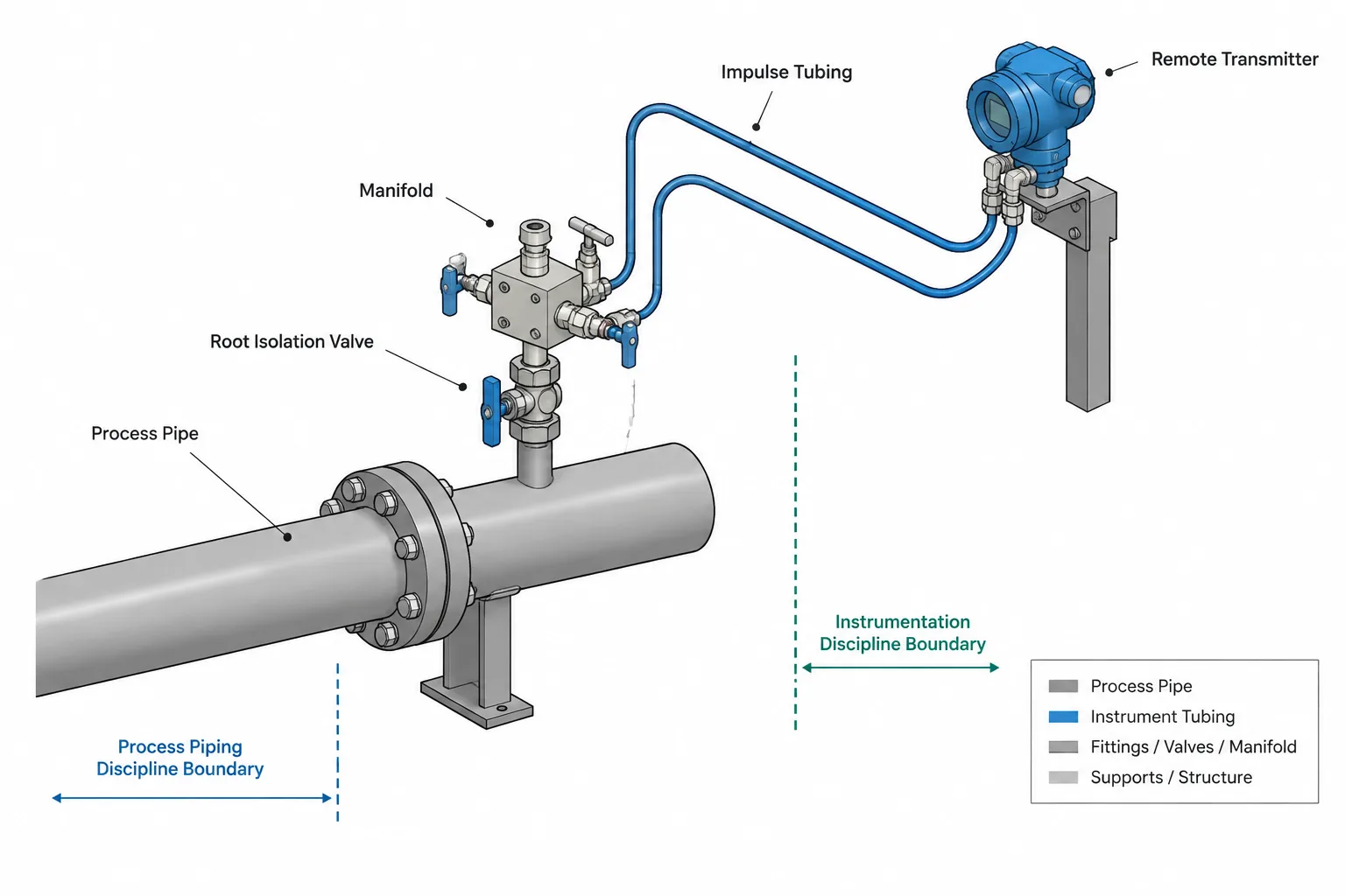
Instrument connections in piping CAD must communicate more than the location of an instrument symbol. The model may need to distinguish the process opening, piping-owned isolation, the instrument interface, and any space required for operation or maintenance.
This reference explains how to divide that assembly into meaningful elements, coordinate discipline ownership, and select a modeling boundary that fits the intended drawing or deliverable. Use it alongside the approved P&ID, piping specification, instrument hook-up, vendor information, and project modeling procedures.
Instrument connections are often small compared with the main piping, but they can create significant design, fabrication, and coordination problems when their purpose or scope is unclear. A symbol on a P&ID may represent a process tap, an isolation valve, impulse tubing, a manifold, and an instrument located some distance from the pipe. Treating that symbol as one generic CAD component can hide important interfaces.
A useful piping model separates the physical process connection from the instrument assembly and identifies which discipline owns each part. The required detail depends on project scope, fabrication strategy, service conditions, and the intended deliverable. A routing model may need only the tap location and access envelope, while a fabrication isometric may need the actual branch components, valve, welds, and termination point.
What Is an Instrument Process Connection?
An instrument process connection is the physical path through which an instrument senses pressure, temperature, level, flow, composition, or another process condition. It begins at the pipe or equipment boundary and may continue through valves, fittings, tubing, manifolds, or protective devices.
The term tap is commonly used for the opening or branch at the process pipe. The tap may be formed with a branch fitting, coupling, boss, nozzle, flange, or another project-approved connection. The word does not, by itself, define the branch construction, reinforcement, end connection, or material.
A root valve is the first isolation valve associated with many instrument connections. It allows downstream instrument components to be isolated from the process. Not every instrument arrangement is identical, so the actual assembly must come from the applicable P&ID, piping specification, instrument detail, and project practices.
Separate the Tap, Root Valve, and Instrument
One of the most useful modeling decisions is to treat the connection as a series of functional elements rather than a single object.
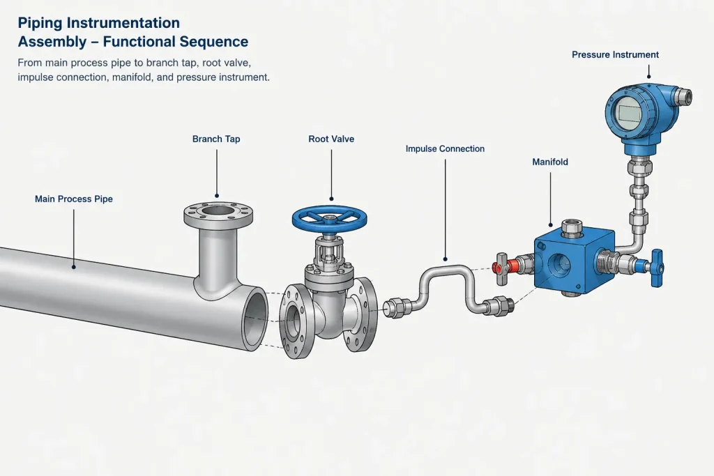
| Element | Typical purpose | Common documentation concern |
|---|---|---|
| Process tap | Creates the opening from the pipe or equipment | Branch type, size, orientation, reinforcement, and attachment |
| Root valve | Provides primary process isolation | Valve type, end connections, operator access, and specification |
| Impulse connection | Transfers process pressure to an instrument | Fittings, tubing or small-bore pipe, slope, support, and routing |
| Manifold | Supports isolation, equalization, venting, or calibration functions | Port arrangement, orientation, access, and instrument compatibility |
| Instrument | Performs measurement or indication | Tag, mounting method, visibility, removal space, and discipline ownership |
This breakdown prevents a common error: placing an instrument symbol directly on the main pipe even though the actual installation requires a branch, isolation valve, and remote mounting arrangement. It also makes scope boundaries visible. For example, piping may supply the branch and root valve, while instrumentation supplies the tubing, manifold, bracket, and transmitter.
Common Connection Categories
Pressure Connections
A pressure connection may serve a local gauge, pressure transmitter, switch, or differential-pressure system. The CAD model should distinguish a direct-mounted instrument from one connected by impulse tubing. Direct mounting can add weight and operating clearance at the pipe, while remote mounting introduces tubing routes, supports, and a separate instrument location.
Differential-pressure measurement normally involves more than one process connection. The two taps and their associated paths must remain identifiable as a related system. Reversing connections, obscuring their relationship, or routing them without regard to process behavior can undermine the measurement arrangement.
Temperature Connections
Temperature measurement often uses a thermowell or another inserted sensing assembly. Unlike a simple pressure tap, this connection has geometry inside the process pipe. The model may need to communicate insertion direction, external projection, connection type, and removal space.
The sensing assembly must not be positioned from appearance alone. Its location can depend on process performance, pipe geometry, mechanical suitability, accessibility, and vendor information. Where internal geometry matters, identify the controlling data rather than assuming that a generic CAD symbol represents the final assembly.
Flow and Differential-Pressure Connections
Flow measurement arrangements may include primary elements, dedicated meter runs, paired taps, manifolds, and carefully arranged impulse connections. The main piping model should preserve the required relationship between the measurement device and nearby fittings or branches. Any required straight-run criteria or tapping arrangement must come from verified project and vendor documents rather than a generic block.
Sampling and Analyzer Connections
Sampling points and analyzer connections can include isolation, pressure reduction, conditioning, drains, vents, and return lines. They should not be reduced to an unlabeled small branch. The destination and function of each connection need to be clear, especially when part of the assembly is supplied on a separate panel or skid.
Orientation Is a Functional Decision
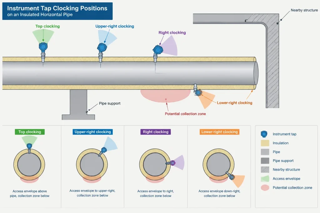
Instrument taps should not be clocked around the pipe only to make the drawing look orderly. Orientation may affect whether gas, liquid, sediment, or condensate enters the sensing path. It can also determine whether the root valve is operable and whether the instrument can be removed.
The preferred orientation depends on the service, measurement method, installation detail, and process requirements. The piping designer should therefore coordinate tap clocking with the process and instrumentation disciplines instead of applying one universal rule.
During layout, check the complete assembly against:
- Nearby pipe, insulation, supports, and structural steel
- Valve operator movement and hand access
- Instrument viewing and calibration access
- Removal paths for gauges, transmitters, manifolds, and thermowells
- Impulse-line routing and support
- Potential vents, drains, pockets, or collection points
- Platforms, walkways, ladders, and personnel exposure
Define the CAD Model Boundary
Modeling every compression fitting and tubing bend is not always useful. Conversely, stopping at the centerline of the main pipe may be insufficient for fabrication or clash detection. The correct boundary should match the model purpose.
A practical arrangement is to define named connection points or ports at discipline interfaces. A port can identify where piping scope ends and instrument tubing scope begins. Its data may include the associated instrument tag, service, nominal connection designation, end connection, orientation, and responsible discipline. Only verified attributes should be populated.
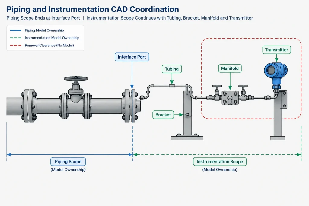
For a general arrangement model, the instrument assembly may be represented by its major physical envelope and connection points. For a detailed fabrication model, piping-owned components should be modeled with the geometry needed to establish cut lengths, weld locations, and material quantities. Very small fittings can remain schematic when they do not affect the intended deliverable, provided the omission is understood and documented.
Documentation Across Drawings and Lists
The same instrument connection appears differently across project documents. The P&ID explains process function and isolation intent. The piping model establishes physical location and orientation. An isometric communicates fabrication components and welds. Instrument documents define the instrument, manifold, tubing, hook-up, and signal information.
These documents should agree on the connection identity without being forced to show identical levels of detail. Useful cross-document checks include:
- The instrument tag on the P&ID matches the tag associated with the model connection.
- The modeled tap is on the correct line or equipment nozzle.
- The connection type agrees with the piping material specification and instrument hook-up.
- The isometric includes all piping-scope components needed for fabrication.
- The tubing or instrument interface has a defined termination point.
- Orientation notes do not conflict with the physical model.
- Items excluded from the piping bill of material are not accidentally counted.
Common CAD and Detailing Errors
- Using a generic tap for every service: A visual marker does not define branch construction or end preparation.
- Modeling only the instrument: This omits the process opening, root valve, and fabrication scope.
- Assigning an arbitrary orientation: Clocking can affect measurement performance, drainage, access, and safety.
- Ignoring insulation: A valve or fitting that clears bare pipe may become inaccessible after insulation is applied.
- Placing tags without stable associations: Free text can become separated from the correct connection during model revisions.
- Double-counting components: Piping and instrumentation bills may both include the same valve, manifold, or fitting if ownership is not defined.
- Assuming the CAD block is fabrication-ready: Symbolic geometry may not represent actual dimensions, bore, engagement, or vendor configuration.
A Practical Review Workflow
Start with the P&ID and instrument index to identify the measurement function and associated tags. Determine the physical process connection from approved piping and instrument details. Confirm which components belong to piping, instrumentation, equipment, or a vendor package.
Next, place the tap on the correct line and set its orientation using the functional installation requirements. Add piping-scope isolation and connection components. Represent the remaining assembly at a level appropriate for coordination, then check access, removal, insulation, structure, and nearby routing.
Finally, reconcile the model with isometrics, bills of material, instrument hook-ups, and vendor information. Mark unresolved connection types or dimensions as pending rather than filling gaps with assumed data. A well-documented interface is more useful than a detailed model built from unverified geometry.
Managing Instrument Connection Data Through Revisions
Instrument connections should remain traceable as the P&ID, piping layout, instrument details, and vendor information develop. A connection that is still schematic should not appear to be fully resolved merely because detailed-looking CAD geometry has been placed in the model.
Where the project system permits, distinguish verified data from provisional information. Useful status subjects include connection construction, ownership, orientation, termination point, mounting arrangement, and the source document controlling the selection. Pending information should be visible to reviewers rather than hidden in object names, informal notes, or generic geometry.
Keep the Interface Stable
The interface between piping and instrumentation should have a persistent identity linked to the applicable line, equipment item, and instrument tag. This helps prevent the connection from being duplicated or abandoned when instruments are relocated, tags change, or small-bore routing is revised.
If the detailed instrument assembly is maintained in another model or document, the piping model should still retain enough information to show where the handoff occurs. The interface representation should support coordination without implying unverified fabrication detail.
Review Changes by Function, Not Appearance
A small graphical change can alter fabrication scope, accessibility, isolation capability, or material takeoff. When a connection is revised, review the effect on the process tap, root valve, instrument routing, support arrangement, insulation clearance, removal path, isometric, and bill of material.
Replacing a generic component with vendor geometry does not complete the review by itself. Confirm that the geometry represents the intended connection and that ownership, specification, orientation, and document references remain consistent.
Model Acceptance Questions
- Can reviewers identify the physical process boundary and the downstream instrument interface?
- Is each modeled component assigned to the correct discipline or package scope?
- Does the representation match the detail level required by the deliverable?
- Are access, operation, calibration, and removal needs represented or reserved?
- Can the connection be traced to its P&ID function and instrument identity?
- Are unresolved selections clearly marked instead of being inferred from generic CAD geometry?
- Will material extraction avoid omitted items and duplicate counting?
The goal is not maximum geometric detail. It is a coordinated representation that communicates function, physical scope, ownership, and remaining design decisions without overstating what has been verified.
Frequently Asked Questions
What should be included in a piping CAD model for an instrument connection?
Include the physical elements needed for the model’s purpose. A coordination model may show the tap, root valve, interface point, and major access envelope. A fabrication deliverable may require the piping-owned branch components, connections, weld locations, and termination point. The project deliverable requirements should control the level of detail.
Is a process tap the same as a root valve?
No. The process tap is the opening or branch from the pipe or equipment. The root valve is an isolation component associated with the connection. Their construction, ownership, and documentation requirements should be identified separately.
Who owns the tubing and manifold?
Ownership depends on the project execution plan, specifications, purchase packages, and discipline practices. Piping may end at the root valve or another defined interface, while instrumentation may provide downstream tubing and manifold components. The boundary must be documented rather than assumed.
Can a generic instrument CAD block be used for fabrication?
A generic block can communicate function or reserve space, but it should not be treated as fabrication geometry unless its construction and dimensions have been verified for that purpose. Symbolic geometry may omit actual connections, engagement, operating clearance, and vendor configuration.
Why does tap orientation require multidisciplinary review?
Orientation can influence process behavior in the sensing path, root-valve access, impulse routing, drainage, visibility, insulation clearance, and instrument removal. Process, piping, instrumentation, and maintenance requirements may all affect the final location.
How should unresolved connection information be shown?
Mark the affected attribute or assembly as pending and identify the controlling document or responsible discipline where the project system allows. Avoid selecting a plausible-looking component merely to make the model appear complete.