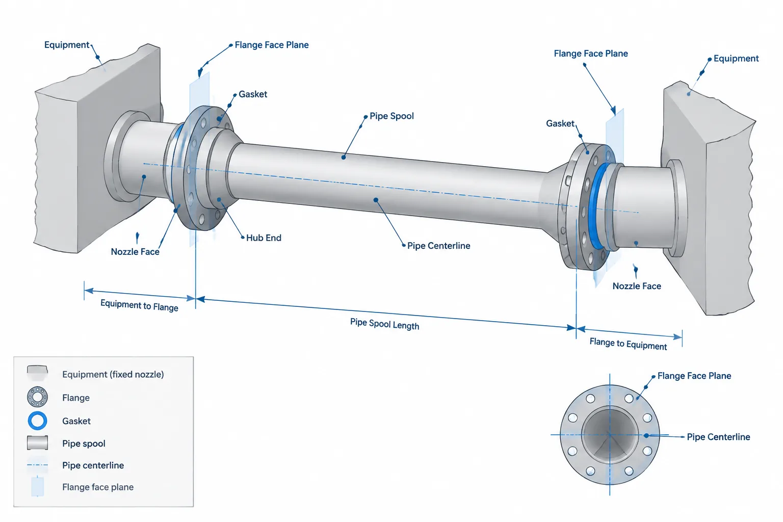
Accurate flanged piping dimensions depend on more than the visible edges of a CAD solid. The controlling geometry comes from defined interface planes, verified component data, and a consistent convention for representing each joint.
This guide explains how flange faces, gasket or joint separation, weld ends, insertion references, and component face-to-face lengths affect layout control and pipe cut-length calculations. It is intended to help designers distinguish coordination dimensions from fabrication dimensions before issuing a model or spool drawing.
Flanged piping can look simple in a CAD model: place two flanges, connect them with pipe, and add a gasket between mating faces. The dimensional logic is more demanding. A designer must know which face or end plane controls each measurement, whether a dimension describes a loose component or an installed assembly, and which values may be used to derive pipe cut length.
These distinctions become especially important around equipment nozzles, valves, removable spools, and mixed flange types. Measuring to the wrong plane can produce a spool that is too long, an incorrect equipment offset, or a flange joint that appears closed in the model but cannot be assembled as detailed.
The reference planes that matter
A flange has several potentially useful reference locations. They should not be treated as interchangeable.
| Reference | What it represents | Typical use |
|---|---|---|
| Flange face | The mating surface presented toward the adjoining flange or component | Spool overall dimensions, nozzle interfaces, and valve installation |
| Gasket contact surface | The portion of the facing intended to contact the gasket | Joint detailing and gasket compatibility checks |
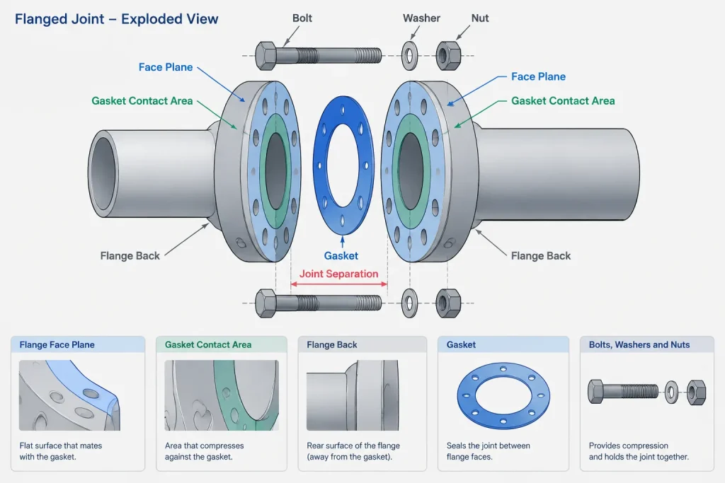
| Back of flange | The rear surface around the bolt circle | Bolt-length studies, wrench access, and flange thickness checks |
| Hub or weld-end plane | The pipe-side end of a weld neck or similar transition | Pipe cut-length calculations and weld location control |
| Pipe end or insertion reference | The location where pipe terminates or seats in a flange connection | Slip-on, socket-weld, threaded, or other assembly-specific detailing |
| Pipe centerline | The longitudinal axis of the pipe and flange bore | Routing, alignment, elevations, and branch geometry |
A dimension labeled only as “to flange” is incomplete if several flange planes could satisfy the wording. Drawings should identify the intended reference, commonly the face of flange, flange weld end, or pipe centerline intersection.
Face of flange is an interface datum
The face of flange is often the most useful external datum because it defines where a spool interfaces with another spool, a valve, or an equipment nozzle. A face-to-face dimension for a fabricated spool normally describes the distance between its two exposed flange faces before installation.
That standalone spool dimension is different from the distance occupied by a complete installed arrangement. When two mating flanges are assembled, the joint includes a gasket and may include other specified elements. The final relationship between the two face planes depends on the selected joint design and controlled assembly data.
CAD users should therefore avoid automatically making mating flange faces coincident. Coincident faces may be a convenient simplified modeling convention, but they do not represent every physical joint. If joint thickness affects an equipment location, overall train length, or closure spool, it must be handled explicitly according to project practice and verified component information.
Raised faces and other facings
On a flange with a raised face, the mating datum is generally associated with the raised sealing surface rather than the surrounding outer flange body. Other facing arrangements can use different contact geometry. A generic block that models only the flange outside diameter and total thickness may not provide enough information to locate the true mating plane.
The flange face plane should be encoded consistently in a CAD component’s insertion point, port, or connection definition. If one library component uses the sealing face while another uses the front of the flange body, swapping components can shift the connected piping without an obvious visual warning.
Gasket thickness is not automatically a layout allowance
A gasket has a supplied thickness, but its installed behavior depends on the gasket construction, facing, bolting, and assembly procedure. Designers should not invent a compressed thickness or apply a universal gasket allowance to every flanged joint.
For dimensional control, use the project-approved convention or verified joint information. Depending on the workflow, a model may:
- Represent the gasket as a separate component with controlled nominal geometry.
- Use a defined joint separation embedded in the connection rules.
- Omit physical gasket geometry while tracking the gasket in component data and material lists.
- Use simplified coincident faces for general arrangement work but apply joint allowances in fabrication calculations.
Any of these methods can be workable if used consistently and documented. Problems arise when different disciplines assume different conventions. For example, a layout model may omit gasket space while a spool-detailing workflow adds it again, producing a duplicated allowance.
How flange type changes the pipe-side reference
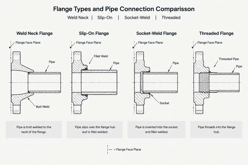
The face plane controls the external interface, but pipe cut length depends on what happens behind that face. Different flange types connect to pipe in different ways.
Weld neck flanges
A weld neck flange has a hub that transitions from the flange body to a butt-weld end. For cut-length work, the important component dimension is the distance from the flange face to the weld-end plane. The pipe normally begins at that weld end, subject to the approved weld preparation and fabrication convention.
For a straight spool with a weld neck flange at each end, the conceptual relationship is:
pipe cut length = required spool face-to-face length - left flange face-to-weld-end projection - right flange face-to-weld-end projection - applicable fabrication adjustments
This is a dimensional framework, not a substitute for verified flange dimensions or shop rules. Weld gaps, bevel references, and trimming allowances must follow the applicable fabrication documents.
Slip-on flanges
A slip-on flange overlaps the pipe rather than ending at a butt-weld plane. Its pipe cut length cannot be derived by applying weld neck flange geometry. The pipe-end location relative to the flange face, insertion position, and weld arrangement must be based on the approved detail or fabrication practice.
A simplified CAD model may show only the flange body and pipe outside diameter. That is adequate for some space studies but insufficient for fabrication cut lengths unless the hidden overlap relationship is stored or documented elsewhere.
Socket-weld and threaded flanges
Socket-weld and threaded flanges also use connection-specific engagement geometry. The relevant pipe-end location is not necessarily visible from the outside of an assembled model. Cut lengths should come from verified insertion or engagement rules rather than from the apparent gap between modeled solids.
This is why changing the flange type in a model is more than a graphical substitution. The connection behavior, pipe termination, weld or thread information, and material description must change with it.
Component face-to-face dimensions inside a flanged run
Valves, strainers, inline instruments, and other flanged components often have a controlled face-to-face or end-to-end length. That length should be treated as component data, not estimated from a scaled symbol or catalog image.
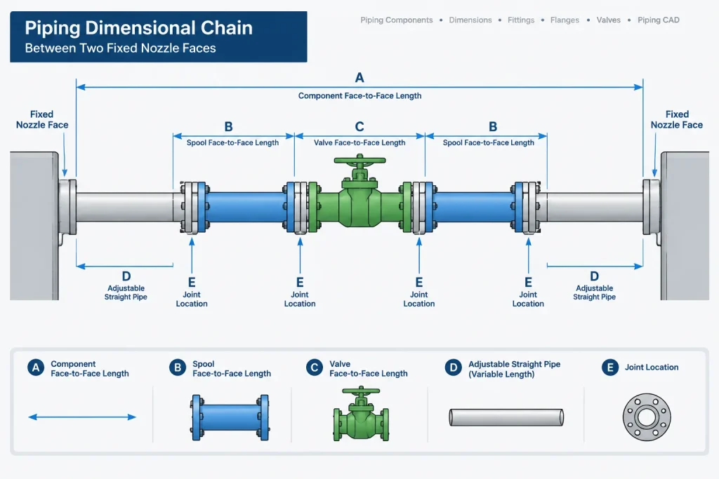
A dimensional chain between two fixed nozzle faces may include:
- The controlled separation at each flange joint.
- The face-to-face length of each inline component.
- Flanged spool face-to-face dimensions.
- Reducer, fitting, and branch takeouts.
- Any project-approved field-fit or closure provision.
The available distance should be reconciled against the complete chain. Do not force a model to close by stretching a flange, scaling a valve, or moving an equipment nozzle away from its controlled location.
A practical CAD workflow
- Establish fixed interface datums. Identify equipment nozzle faces, existing flange faces, battery limits, or other surveyed and vendor-controlled points.
- Confirm the flange connection type. Record the facing, end connection, nominal size, material class, and other project-required attributes.
- Use verified component geometry. Obtain flange projections and component face-to-face lengths from the governing dimensional source or approved manufacturer information.
- Declare the joint convention. Determine whether gasket or joint separation is modeled, embedded in connection logic, or handled during fabrication detailing.
- Build the dimensional chain. Work from the fixed interfaces toward the adjustable straight pipe segments rather than measuring arbitrary solid edges.
- Derive cut lengths by connection type. Apply the correct face-to-end, overlap, insertion, or engagement relationship for each end.
- Check the bill of material. Confirm that modeled flange types, gaskets, fasteners, and adjoining components agree with the component data.
- Review replacement and assembly access. Verify that the joint can be opened and that removable components have a practical extraction path.
Common modeling and detailing errors
- Dimensioning to the back of a flange: This makes the result dependent on flange thickness and does not directly control the mating interface.
- Making every pair of faces coincident: This can hide the installed joint separation and distort an overall dimensional chain.
- Adding gasket thickness twice: The CAD connection rule may already include the allowance used again in a manual calculation.
- Using flange body thickness as face-to-end projection: A hubbed flange includes geometry beyond the main flange body.
- Replacing flange types without recalculating pipe: A new end connection can change the pipe termination and cut length.
- Reading dimensions from a schematic block: P&ID symbols and simplified plan symbols are not fabrication geometry.
- Ignoring vendor-defined faces: Equipment and specialty items may use interface points that must be confirmed from approved data.
What drawings should communicate
A fabrication or installation drawing should make the controlling dimension clear without requiring the reader to inspect the model’s internal origin points. Use explicit terminology such as “face of flange to face of flange” where that is the intended requirement. Show weld locations, field-fit provisions, and connection types separately from overall dimensions.
For general arrangements, dimensioning to flange faces usually provides a stable coordination datum. For spool drawings, supplement face-to-face dimensions with the information needed to establish actual pipe cuts and end preparation. If gasket space or another joint element is included in a dimension, state that convention rather than leaving it to interpretation.
Final check: interface dimensions before solid geometry
The most reliable flanged piping models are controlled by interface planes and connection data, not by the apparent edges of solids. Start with fixed flange faces, apply verified component lengths, define how joints are represented, and derive straight-pipe lengths from the selected end connections.
This approach keeps layout dimensions, spool details, material data, and field assembly aligned. It also makes component replacement safer because a revised valve or flange can be checked against known interface datums instead of being forced into geometry that only looks correct.
Model-review and handoff considerations
A flanged piping model should remain understandable when it passes from layout to stress review, fabrication detailing, construction, or maintenance planning. Visible geometry alone may not reveal whether a joint gap is modeled, whether a flange port is located at the sealing face, or how the pipe end is positioned inside an overlapping connection.
Useful model and drawing metadata can identify the connection type, face reference, pipe-side termination, joint convention, and source of controlled component geometry. This allows another user to audit the dimensional chain without reverse-engineering component solids.
Questions for a dimensional review
- Are the fixed nozzle and flange interface planes clearly identified?
- Do component ports use the same face-plane convention throughout the model?
- Is joint separation represented consistently rather than added in more than one place?
- Are pipe cuts derived from the actual connection behavior instead of flange-body edges?
- Do valve and specialty-component lengths come from verified component information?
- Will changing a flange or connection type trigger a review of the adjoining pipe length?
- Can the drawing reader identify which dimensions control fabrication and which support layout coordination?
These checks help expose hidden assumptions before they become spool-fit or equipment-alignment problems. Final fabrication dimensions should still be confirmed against approved project documents, component information, and shop practices.
Frequently asked questions
Is flange face-to-face length the same as pipe cut length?
No. Face-to-face length controls the external limits of a flanged spool or component. Pipe cut length also depends on the pipe-side geometry of each connection, including a weld-end projection, overlap, insertion, or engagement reference and any approved fabrication adjustments.
Should mating flange faces be coincident in a CAD model?
Only when that is the declared modeling convention. Some workflows model joint separation or gasket geometry, while others use coincident faces and account for the joint elsewhere. The selected method must be consistent across layout and fabrication workflows.
Which flange plane should be used for piping layout dimensions?
The flange face is commonly the most useful interface datum for layout and coordination. Pipe cut calculations may require a different pipe-side reference, such as a weld-end plane or insertion location. Drawings should name the intended reference rather than saying only “to flange.”
Why can changing the flange type alter pipe cut length?
Flange types do not all terminate or engage the pipe in the same way. Replacing a butt-weld connection with an overlapping, socketed, or threaded arrangement changes the relationship between the flange face and the pipe end, even if the external model appears similar.
Can pipe cut length be measured directly from simplified CAD solids?
Not reliably. Simplified solids may omit sealing surfaces, internal sockets, pipe overlap, weld preparations, or connection metadata. Cut lengths should be derived from verified component geometry and the approved fabrication convention.
How can duplicated gasket allowance be avoided?
Document where joint separation is controlled. It may be represented by gasket geometry, embedded in connection logic, or applied during fabrication detailing. Review calculations and model settings together so the same allowance is not applied twice.