Reducing bushing vs. reducing coupling is more than a terminology question. Each fitting creates a different connection chain, occupies space differently, and requires a different installation sequence. Selecting the wrong component in a model or material list can affect adjoining nipples, pipe cut lengths, tool access, and field assembly.
This guide explains how to identify each fitting from its thread arrangement, choose between them based on the available connection, and document the result clearly in CAD models, isometrics, details, and bills of material. Final selection should always be checked against the governing piping specification and approved product data.
A reducing bushing and a reducing coupling can both connect a smaller nominal pipe size to a larger threaded opening, but they do not create the same assembly. Their thread arrangement, external envelope, installation method, and effect on pipe cut length are different. Treating them as interchangeable in a CAD model can create incorrect material lists, inaccessible joints, or field assemblies that do not match the drawing.
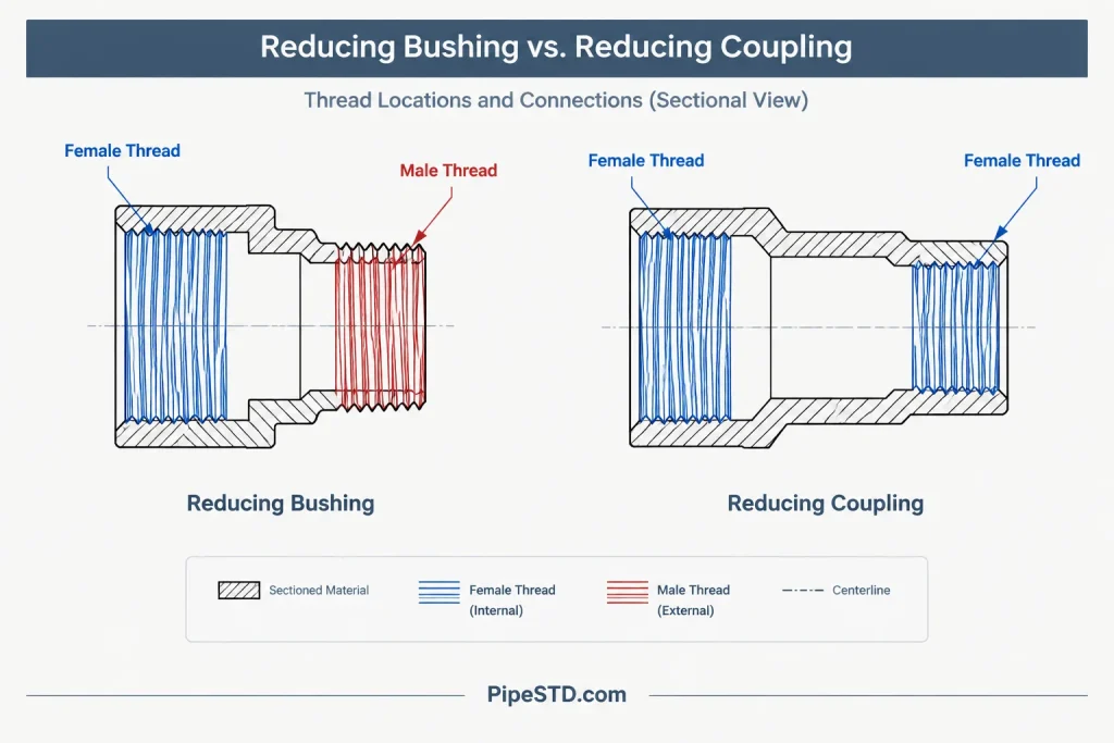
The practical distinction is simple: a reducing coupling is an inline fitting with female threaded connections at both ends, while a typical threaded reducing bushing has a larger male thread on the outside and a smaller female thread through the center. That difference determines where each component can be installed and what additional pipe or fittings are required.
What Is a Threaded Reducing Coupling?
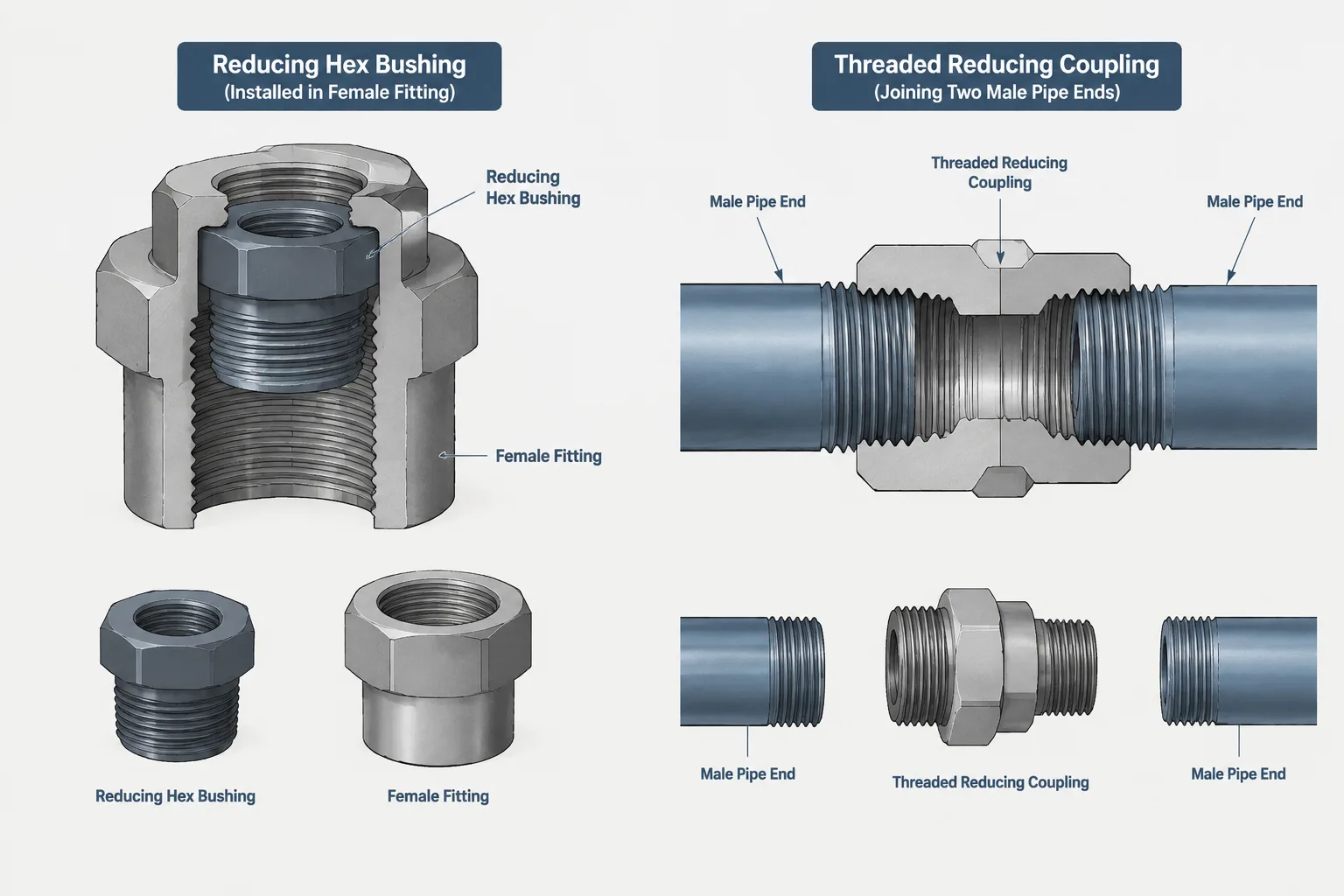
A threaded reducing coupling is used between two male-threaded pipe ends or components of different nominal sizes. One end of the coupling has a larger female threaded opening, and the other has a smaller female threaded opening. The fitting therefore acts as a complete inline transition.
A typical assembly has three separate pieces:
- The larger male-threaded pipe or nipple
- The reducing coupling
- The smaller male-threaded pipe or nipple
Because the coupling has its own body length, it occupies measurable space along the pipe centerline. Its end locations and thread makeup affect the required pipe lengths on both sides. A generic CAD symbol that represents only a change in diameter may be adequate for an early schematic, but fabrication documentation should identify the actual fitting type and use verified dimensional data.
What Is a Threaded Reducing Bushing?
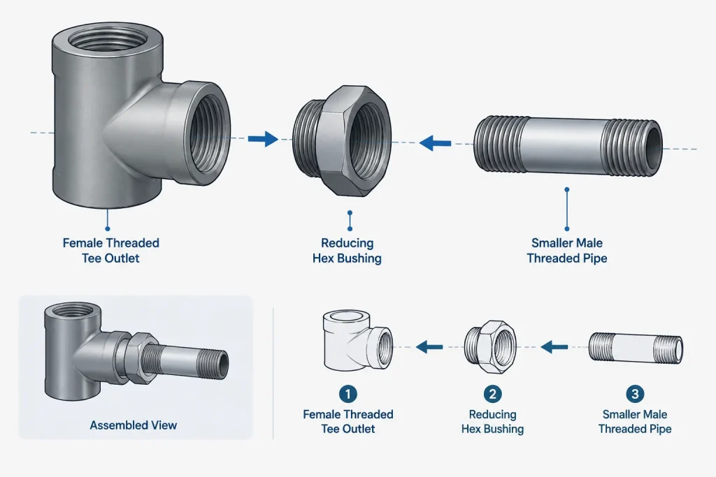
A threaded reducing bushing adapts an existing female threaded opening. Its larger outside thread screws into that opening, while its smaller internal thread receives a smaller male-threaded pipe, nipple, valve connection, instrument connection, or another compatible component.
The bushing does not normally connect directly between two male pipe ends. It depends on a larger female-threaded component to contain its external thread. Common host components may include tees, crosses, couplings, valve bodies, equipment connections, or other fittings, subject to the project piping specification and the limitations of the selected products.
Threaded reducing bushings are commonly encountered in two broad body forms:
- Hex-head bushing: A wrenching portion projects beyond the host fitting and provides external flats for installation.
- Flush bushing: The bushing is intended to sit with little or no projecting hex body, although its exact installed position and driving method depend on the product.
These forms should not be represented by the same detailed CAD geometry when clearance, access, or overall assembly length matters.
Reducing Bushing vs. Reducing Coupling
| Characteristic | Reducing bushing | Reducing coupling |
|---|---|---|
| Typical connection arrangement | Larger male outside thread with a smaller female internal thread | Female threaded opening at each end |
| Required adjoining connection | Installs into a larger female threaded opening | Connects two male-threaded ends |
| Role in the assembly | Reduces an existing fitting or component outlet | Creates a separate inline transition |
| External envelope | Partly contained within the host component; projection depends on body form | Has a distinct fitting body between adjoining pipe ends |
| Effect on cut length | Depends on bushing projection, host fitting geometry, and thread makeup | Depends on coupling length and thread makeup at both ends |
| Installation access | May require access to external flats or an internal driving feature | Requires enough assembly freedom to make up both threaded joints |
| CAD and BOM identity | Should be listed as a bushing with both nominal sizes | Should be listed as a reducing coupling with both nominal sizes |
Why the Components Are Not Automatically Interchangeable
They require different adjoining threads
A coupling receives male threads at both ends. A bushing presents a male thread at its larger end and receives a male thread at its smaller end. Replacing one with the other can require an extra nipple, a different host fitting, or a change in the adjoining component connection.
They create different assembly lengths
A reducing coupling has a body between two pipe ends. A bushing is installed partly within another component. Even when the same two nominal sizes are involved, the face locations and resulting pipe cut lengths can differ. A substitution should therefore trigger a dimensional review rather than a simple BOM description change.
They have different wrench and assembly needs
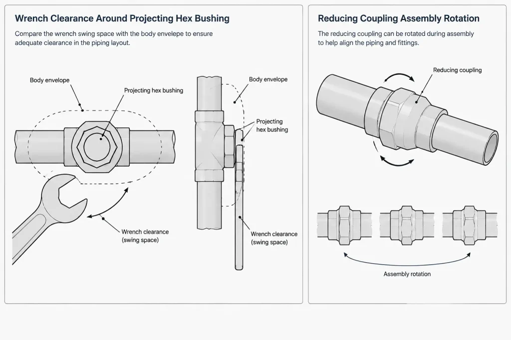
A hex bushing needs clearance around its wrenching flats during installation. A flush design may require access for a different driving method. A coupling introduces two joints that must be assembled in a workable sequence. Nearby fixed equipment, valves, walls, supports, and other piping can prevent the theoretical arrangement from being installed.
The project specification may treat them differently
Material, fitting class, thread form, manufacturing type, service restrictions, and permitted size combinations must come from the governing piping specification and verified product data. The fact that a bushing can be drawn in the available space does not establish that it is permitted for the service.
How to Read and Write the Size Description
Both components are normally identified using the larger nominal size followed by the smaller nominal size, but company naming conventions can vary. The description should also include the fitting type so that the size pair is not mistaken for a reducer, swage nipple, or reducing tee.
Clear descriptions include the following information where required by the project:
- Component type, such as reducing coupling, hex bushing, or flush bushing
- Larger nominal connection size
- Smaller nominal connection size
- Thread or end-connection designation
- Material and applicable fitting classification
- Project commodity code or catalog identifier
Do not infer the thread details from size alone. Nominal pipe size identifies the connection size system; it does not fully define thread form, engagement, material, class, or product geometry.
CAD Modeling and Drafting Considerations
Model the connection logic before adding detail
Each CAD component should have ports that reflect its actual connection arrangement. A reducing coupling should have two female threaded ports of different nominal sizes. A bushing should have a larger male port associated with the host opening and a smaller female port for the outgoing connection. This allows automated connection checks and material reports to distinguish the fittings.
Use verified dimensions for fabrication output
Threaded joint geometry is more complicated than placing pipe ends at the visible faces of a fitting. Engagement and makeup affect the final installed position, while catalog dimensions may use reference points that differ from the CAD system’s insertion points. Use dimensions from the approved project source and confirm how the software defines fitting origins and ports.
Avoid double-counting a bushing
When a bushing is modeled inside the opening of a tee, coupling, or valve, its solids may overlap the host component. That overlap can be intentional because the threads occupy the same physical region. However, the model must still report the bushing as a separate item if it is separately purchased and installed.
Show enough detail for the drawing purpose
A P&ID may only need to show that the line or connection changes size. A fabrication isometric or detailed assembly drawing may need to identify the bushing or coupling explicitly. A coordination model may require only the external envelope, including a projecting hex head where it could conflict with nearby objects.
A Practical Selection Workflow
- Identify the available connection. Determine whether the larger adjoining component provides a male or female threaded end.
- Confirm the required smaller connection. Check the end type of the outgoing pipe, nipple, valve, or instrument component.
- Review the piping specification. Verify that the proposed fitting type, material, classification, and size combination are permitted.
- Check assembly sequence. Confirm that the fitting and adjoining threaded pieces can be rotated, tightened, and later removed if maintenance is expected.
- Check the physical envelope. Include the coupling body or bushing projection rather than representing only a centerline size change.
- Apply verified dimensions. Use the approved fitting standard, manufacturer data, or project catalog rather than scaling geometry from another size.
- Review the BOM and drawing callout. Make sure the reported component type agrees with the modeled connection arrangement.
Common Documentation Errors
- Calling every threaded size transition a reducer without identifying the actual component
- Placing a bushing between two male pipe ends without a female host connection
- Modeling a coupling but listing a bushing in the bill of material
- Ignoring the projection and wrench clearance of a hex bushing
- Assuming thread engagement is equal to the visible fitting depth
- Scaling a fitting from another nominal size instead of using verified geometry
- Changing the fitting type without recalculating adjoining pipe or nipple lengths
- Using a geometrically possible fitting that is not allowed by the project specification
Key Takeaway
The choice between a reducing bushing and a reducing coupling begins with connection geometry, not appearance. Use a reducing coupling when two different-size male-threaded ends require a separate inline fitting. Use a reducing bushing when a smaller female connection must be created within an existing larger female opening, provided the project specification permits it. In CAD and fabrication documentation, preserve that distinction through accurate port types, verified dimensions, clear size descriptions, and an assembly sequence that can work in the field.
Review the Complete Threaded Connection Chain
A reliable design review should follow the assembly from one component to the next rather than examining the size transition in isolation. Identify whether each adjoining connection is male or female, determine which component provides the transition, and confirm that the resulting sequence can actually be assembled. This approach exposes arrangements that look plausible on a centerline drawing but cannot be made up in the field.
The review should also distinguish between fitting geometry and installed geometry. Visible faces do not necessarily represent the effective endpoints of a threaded assembly. Thread makeup, the host component, and the fitting body all influence the final location of adjoining pipe or equipment.
Keep Model Identity and Procurement Identity Aligned
The CAD object name, drawing callout, commodity description, and bill-of-material entry should identify the same fitting type. A generic size-change object may be acceptable during preliminary layout, but it should not silently become fabrication documentation without confirming the actual connection arrangement.
- Record the fitting type rather than describing only the size change.
- Keep the larger and smaller connections in the project-approved order.
- Represent the actual port genders used by connection checking or routing software.
- Include the relevant body form when its projection affects access or clearance.
- Recheck adjoining pipe or nipple lengths whenever the fitting type changes.
Consider Removal as Well as Installation
A threaded assembly may be installable during initial construction but difficult to remove after nearby piping, supports, insulation, or equipment are in place. Maintenance review should consider which item must rotate, where tools must be applied, and whether another connection must be disturbed first. This is especially important where a bushing is recessed into a host component or where a coupling is trapped between fixed connections.
CAD clearance checks can support this review, but they do not establish product compatibility or specification compliance. Confirm thread designation, material, fitting classification, permitted component type, and dimensional references using approved project sources.
Frequently Asked Questions
Can a reducing bushing be installed in a threaded coupling?
A bushing can only be installed where a compatible larger female threaded opening is available. A coupling may provide such an opening, but the complete combination must still comply with the piping specification, product limitations, required connection arrangement, and available installation access.
Why can a reducing bushing make the assembly appear shorter?
Much of the bushing is contained within its host component, while a reducing coupling has a separate body positioned between adjoining male-threaded ends. The actual difference cannot be determined from appearance alone because body form, host geometry, and thread makeup affect installed locations.
Should a bushing be shown as a separate item in the bill of material?
When the bushing is separately purchased and installed, it should normally retain a separate component identity even if its CAD solid overlaps the host fitting. Project material-management rules and commodity coding determine the final reporting method.
Can the same CAD symbol represent both fitting types?
A generic size-transition symbol may be sufficient for a conceptual diagram, but detailed models and fabrication documents should distinguish the fittings. Their port genders, envelopes, assembly requirements, and effects on adjoining components are not the same.
What should be reviewed when substituting a coupling for a bushing?
Review the adjoining thread genders, required nipples or adapters, fitting envelope, assembly sequence, wrench access, maintenance access, pipe cut lengths, material list, drawing callouts, and compliance with the governing piping specification.