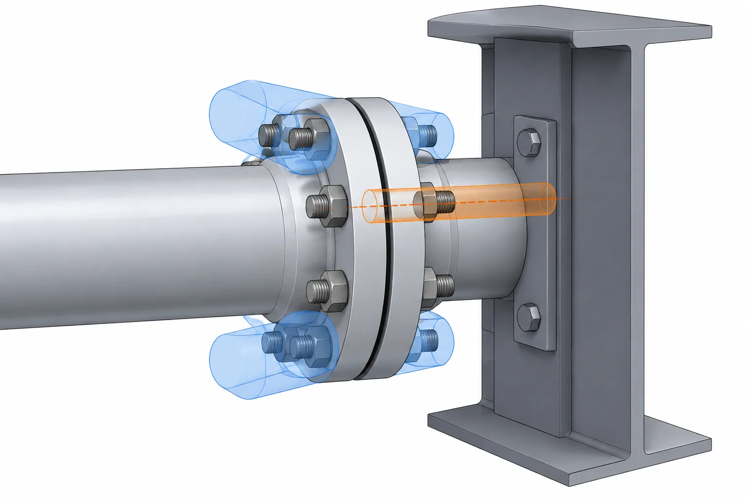
Flange bolting access in piping CAD is a constructability and maintenance issue, not merely a geometric clash check. A connection may appear complete in the model while a nearby structure, valve body, insulated line, or equipment surface prevents workers from inserting fasteners or operating the intended tool.
This guide explains how to evaluate the working space around a flange joint without treating a generic clearance envelope as a universal requirement. The review should be based on the actual joint arrangement, verified component geometry, anticipated construction sequence, maintenance condition, and project-approved tooling information.
A flange joint can fit geometrically in a piping model yet remain difficult or impossible to assemble. The pipe centerlines may align, the flange faces may meet, and the bolt holes may be correctly oriented, but nearby steel, equipment, insulation, or another pipe can block access to the bolting.
Checking flange bolting access in CAD means looking beyond the outside diameter of the flange. Designers must consider how studs or bolts enter the joint, how nuts are started and tightened, which tools may be used, and whether the joint can later be dismantled. These checks are especially important in congested racks, equipment connections, valve stations, modular assemblies, and piping installed close to walls or structural members.
Bolting Access Is More Than Flange Clearance
A basic clash check typically confirms that the flange body does not intersect another modeled object. That is necessary, but it does not establish that the joint is constructible or maintainable.
A practical access review considers several related spaces:
- Hardware envelope: The physical space occupied by studs or bolts, nuts, and washers where applicable.
- Insertion path: The axial space needed to place a bolt or stud through the flange holes.
- Tool envelope: The space needed around the nut for the selected wrenching or tensioning method.
- Hand access: Room for workers to position hardware, engage threads, and operate tools safely.
- Disassembly path: Space for removing corroded, damaged, or fully assembled hardware during maintenance.
These envelopes are not necessarily identical. A nut may fit beside a structural member while the wrench required to turn it does not. A stud may be installable before adjacent piping is erected but may have no removal path after the plant is complete.
Studs, Machine Bolts, and the Direction of Installation
The modeled joint should reflect the bolting arrangement required by the piping specification, equipment supplier, valve design, or project practice. A generic cylinder passing through the flange holes may be enough for visual representation, but it is not always enough for an access study.
Stud Bolts
A stud typically projects beyond the nuts on both sides of a joint. The access check therefore needs to include the complete joint stack-up and the expected projections, not merely the distance between the outer flange faces. The model should also allow for the fact that the stud must reach its installed position somehow.
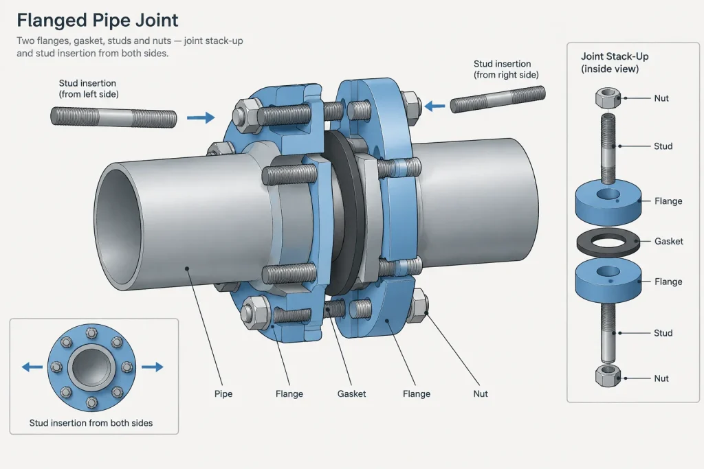
If a stud can be inserted from either side, the less obstructed direction may be used during assembly. That flexibility should not be assumed when one side is blocked by a valve body, equipment casing, wall, or closely spaced flange.
Machine Bolts or Cap Screws
Some assemblies use headed bolts or threaded holes rather than studs with nuts on both ends. These arrangements create different access conditions. A bolt head still requires holding or turning clearance, while a cap screw must have a clear path into its threaded hole. The actual connection detail must be verified rather than inferred from a generic flange symbol.
Installed Hardware Is Not the Entire Path
A common modeling mistake is to check only the final position of the fastener. Installation requires a swept path from an accessible starting position to that final position. For a straight stud, this is generally an axial movement aligned with the bolt hole. If the path intersects steel or equipment, the stud cannot be installed from that side even if its final modeled position is clash-free.
Tool Clearance Around the Nuts
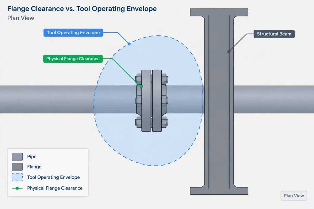
Tool access depends on how the joint will be tightened. An open-end wrench, box wrench, socket, hydraulic torque tool, and bolt tensioning system do not occupy the same space. Tool selection may also change with bolt size, service requirements, site practices, and contractor procedures.
CAD should therefore avoid presenting one arbitrary tool envelope as universally valid. Instead, the model or review markup can identify restricted joints and request confirmation of the intended bolting method. For critical or highly congested joints, a project-approved clearance template can be created from verified tool information.
| Access condition | CAD question | Typical coordination action |
|---|---|---|
| Radial nut access | Can a tool engage the nut without striking adjacent objects? | Check a tool envelope around each nut position. |
| Tool reaction space | Can the tightening tool operate and react as intended? | Confirm the planned tool type and orientation. |
| Axial fastener access | Can the stud or bolt move into and out of the hole? | Model or sweep the insertion path from both sides. |
| Worker approach | Can personnel reach the joint from a platform or accessible area? | Coordinate access routes, platforms, and nearby piping. |
| Future removal | Can hardware be removed after surrounding construction is complete? | Review the final operating arrangement, not only erection sequence. |
Obstructions Commonly Missed in CAD Reviews
Bolting access conflicts are often caused by objects that are simplified, hidden, or added late in design. Typical examples include:
- Structural beams, columns, braces, handrails, and grating frames.
- Adjacent pipe insulation and removable insulation covers.
- Valve bodies, gear operators, actuators, and position indicators.
- Equipment casings, nozzle reinforcement, baseplates, and support clips.
- Pipe shoes, guides, clamps, trunnions, and spring-support hardware.
- Cable tray, conduit, instrument tubing, and local control panels.
- Walls, floors, trenches, curbs, and concrete housekeeping pads.
- Other flange joints whose own bolting envelopes overlap the first joint.
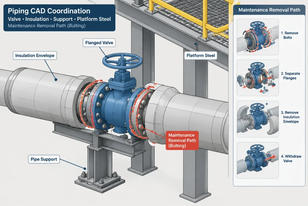
Insulation deserves particular attention. A bare-pipe model may show generous access, while the finished insulated system leaves little room for a wrench or hand. Removable flange covers may help with maintenance, but their thickness, closure arrangement, and removal direction must still be coordinated from verified project information.
Flanges at Equipment and Valve Connections
Equipment nozzles and flanged valves often create asymmetric access. One side of the joint may be open while the other is close to a body casting, support foot, actuator bracket, or nozzle neck. Standard-looking flange geometry does not guarantee uniform access around every bolt position.
Supplier drawings should be reviewed for more than face-to-face or nozzle projection dimensions. Useful interface information includes the body envelope, local ribs, covers, operator supports, and any restrictions on bolt installation. If supplier geometry is incomplete, the CAD model should clearly identify the uncertain area rather than treating a simplified placeholder as verified clearance.
Wafer-style components can create an additional concern because long bolting may pass through multiple flanges and the component body. The insertion direction and available length must be checked against adjacent piping and structures. The final bolting arrangement should come from the applicable specification and verified component data.
A Practical CAD Checking Workflow
1. Identify Joints That Need Detailed Review
Not every flange requires a fully modeled tightening tool. Prioritize congested joints, equipment interfaces, large or heavy hardware, joints beside structural steel, and connections expected to be opened for routine maintenance.
2. Confirm the Joint Stack-Up
Verify which components form the joint, including the two flange faces, gasket, washers if specified, and bolting type. Avoid deriving bolt length from a visually simplified assembly.
3. Represent the Fasteners at Useful Detail
Use lightweight geometry for general coordination and more detailed geometry for problem locations. At minimum, the representation should distinguish the nut envelope and axial fastener path. Excessive thread detail usually adds model weight without improving access decisions.
4. Test Both Installation Directions
Check whether the fastener can enter from either side. Record a required direction when only one side is workable. Do not rely on workers discovering the direction after surrounding items have been installed.
5. Apply a Verified Tool Envelope
Where tightening clearance is critical, use an envelope based on the intended tool or a project-approved conservative template. Keep the clearance object on a dedicated layer, class, or review status so it is not mistaken for permanent plant geometry.
6. Review the Final Maintenance Condition
Repeat the check with insulation, platforms, supports, neighboring lines, and vendor items visible. Consider whether the joint can be opened without dismantling unrelated systems. If removal of another component is intentional, document that maintenance dependency.
7. Communicate Unresolved Restrictions
Use model issues, drawing notes, or coordination markups to identify restricted bolt positions and required installation directions. A generic note such as “provide access” is less useful than a location-specific statement describing the obstruction and needed verification.
How to Document Bolting Access Without Over-Dimensioning
Fabrication drawings and piping isometrics normally should not be crowded with dimensions for every wrench movement. Bolting access is often best controlled through the coordinated model, targeted details, and review comments.
Documentation may include:
- A plan, elevation, or section showing the obstructed bolt position.
- An installation arrow indicating the required fastener direction.
- A temporary clearance envelope placed on a non-plotting review layer.
- A note requiring confirmation against supplier or construction information.
- A maintenance-removal view for a valve or frequently opened joint.
Any envelope used for clearance checking should be labeled by purpose. It should not imply that the represented space is mandated by a standard unless that requirement has actually been verified.
Designing for Assembly and Maintenance
Good flange layout accounts for the process of building and servicing the joint, not only its finished appearance. Small routing changes, flange rotation where permitted, revised support placement, or relocation of a nearby obstruction can prevent difficult field work. These changes are usually easier to make during model coordination than during construction.
The key distinction is between component clearance and work clearance. Component clearance prevents physical overlap. Work clearance allows people, fasteners, and tools to assemble and maintain the system. A complete flange review needs both.
Turning an Access Conflict Into a Useful Model Issue
A bolting-access issue should identify the affected joint, the obstructed fastener position, and the activity that cannot be completed. This distinction helps the responsible disciplines understand whether the conflict concerns hardware placement, tool operation, worker approach, insulation, or future disassembly.
Useful issue descriptions can state whether access is blocked from one side or both sides, whether the obstruction is permanent or removable, and whether the conclusion depends on incomplete supplier geometry. Where a particular installation sequence appears necessary, it should be documented as a coordination condition rather than left as an informal assumption.
Separate Verified Geometry From Allowance Geometry
Permanent components, temporary tool envelopes, maintenance-removal zones, and uncertain supplier areas should remain visually distinguishable in the CAD environment. Clear naming, display styles, and review status help prevent an allowance object from being mistaken for fabricated plant geometry.
A clearance envelope also needs traceable intent. Reviewers should be able to tell whether it represents a fastener path, nut-access zone, tool operating space, hand-access allowance, or removable-component path. Combining these different needs into an unexplained volume can conceal the real cause of a conflict.
Coordinate Changes With the Joint Requirements
Resolving an obstruction may involve rerouting a nearby line, revising a support, changing the approach to the joint, or adjusting flange orientation where the governing design permits it. Any change must preserve required alignment, connection details, component operation, and applicable project requirements. Access should not be improved by altering verified bolting or flange information without engineering review.
Final Review Questions
- Does the model show the actual connection arrangement rather than a generic flange placeholder?
- Can every fastener reach its installed position from an available approach?
- Can the intended tool engage and operate without contacting permanent or temporary obstructions?
- Have insulation, supports, vendor items, platforms, and neighboring systems been included in the review?
- Can the hardware be removed in the completed maintenance condition?
- Are required installation directions and unresolved supplier-data questions documented?
- Is responsibility for each remaining access conflict assigned through the project coordination process?
Frequently Asked Questions
Why is a standard CAD clash check insufficient for flange bolting?
A clash check usually evaluates objects in their final positions. It may not represent the swept path of a stud, the movement of a wrench, the approach of a worker, or the space needed to remove hardware later.
Should every flange include a detailed wrench model?
Not necessarily. Lightweight clearance geometry is usually more practical for general coordination. Detailed tool geometry is most useful at restricted or critical joints and should be based on verified project or tool information.
Can bolting access be accepted if the joint is assembled before nearby piping?
Construction sequence may make initial assembly possible, but it does not automatically provide future maintenance access. The completed arrangement should also be reviewed unless dismantling adjacent systems is an intentional and documented requirement.
Does rotating a flange always solve an access problem?
No. Rotation may relocate bolt positions, but it must remain compatible with the mating connection, permitted orientation, component geometry, and governing project requirements. It may also transfer the conflict to another fastener location.
How should incomplete vendor geometry be handled?
Mark the affected area as unverified and retain the access issue until suitable supplier information is available. A simplified equipment or valve model should not be treated as proof that bolting clearance exists.
Should insulation be hidden during a bolting-access review?
Both conditions can be useful. The bare joint helps reviewers understand the connection, while the completed insulated condition reveals restrictions created by insulation and removable covers. Maintenance assumptions should be clearly identified.