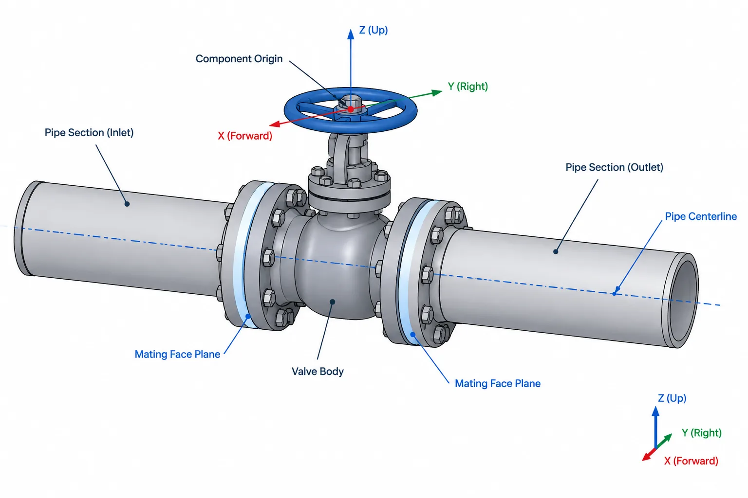
Reliable piping models depend on more than accurate visible geometry. The hidden references that control insertion, connection, rotation, and substitution determine whether a component behaves correctly within a pipe run.
This guide explains how piping CAD connection points relate to component origins, centerlines, reference planes, and orientation controls. It also provides a practical framework for evaluating component replacement without assuming that the insertion point and physical connection boundary are the same.
A piping component can look correct in a CAD model while still being defined incorrectly. Its body may have the right general shape, but an unsuitable insertion origin, misplaced connection port, or inconsistent orientation axis can cause alignment errors, unreliable replacement, and incorrect spool dimensions.
Piping CAD connection points are the geometric and data references used to place components and connect them to pipe, fittings, valves, flanges, equipment nozzles, and other objects. The exact implementation varies by CAD platform and company workflow, but the underlying principles are broadly applicable. A dependable component needs clearly defined ports, a logical origin, a repeatable coordinate system, and reference planes that agree with the dimensions used for design and fabrication.
Connection Points Are More Than Snap Locations
A simple drafting block may use visible endpoints or centerline intersections as snap locations. An intelligent piping component generally requires more information. Each connection may need a location, direction, nominal size, end type, and relationship to the component body.
Even in a non-intelligent model, designers benefit from treating connection locations as controlled references rather than convenient points selected by eye. This makes components easier to align, rotate, replace, and dimension.
A connection definition commonly involves the following concepts:
- Port location: The point where the connected component or pipe is intended to terminate.
- Port direction: The axis pointing into or away from the component connection.
- Centerline: The theoretical axis of the connected pipe or fitting.
- Reference plane: A face, end, center plane, or other surface from which dimensions are controlled.
- Component origin: The local coordinate-system origin used for insertion, rotation, and transformation.
- Orientation axis: A secondary direction that controls roll, clocking, or the component’s local up direction.
Origin, Port, and Reference Plane Are Not Always the Same
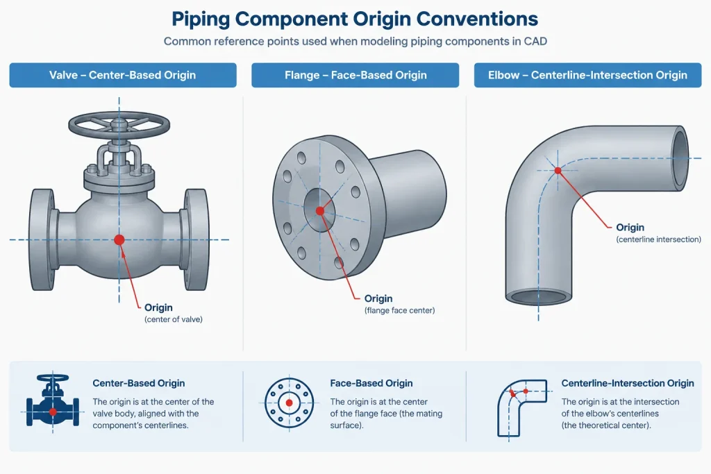
The component origin is not automatically a physical connection point. A two-ended valve might use its geometric center as the origin while placing ports at its end faces. An elbow might use the theoretical intersection of its centerlines as an origin, even though neither pipe connection occurs at that point. A flange could use the face center, bore center, or back-of-flange plane depending on the library convention.
These choices are not necessarily wrong. Problems arise when the convention is undocumented or changes between otherwise similar components.
| Reference | Primary purpose | Typical risk if misused |
|---|---|---|
| Component origin | Insertion, transformation, and replacement | The component shifts when its size or type is changed |
| Connection port | Joining components and establishing the run axis | Gaps, overlaps, or incorrect pipe termination |
| End or face plane | Controlling end-to-end or face-to-face geometry | Incorrect assembly length or dimension baseline |
| Center plane | Symmetric placement and equipment alignment | Unexpected movement when geometry is mirrored or replaced |
| Orientation axis | Controlling roll and rotational position | Operators, branches, or bolt patterns rotate unexpectedly |
How Port Locations Affect Piping Geometry
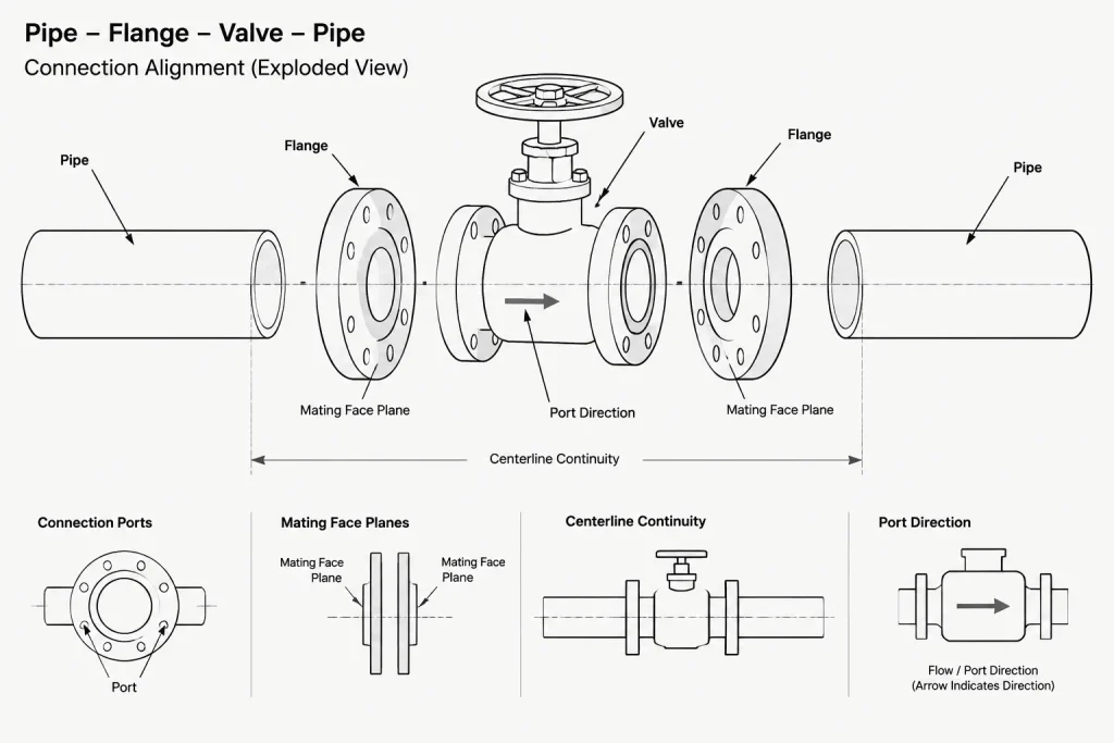
A port should correspond to the intended connection boundary, not merely the visible end of simplified graphics. For a butt-weld component, the port will generally relate to the weld-end plane. For a flanged component, the relevant connection boundary is normally associated with the mating face. Threaded, socket-weld, grooved, mechanical, and proprietary connections may require different geometric interpretations.
The visible solid may omit small details, use symbolic geometry, or represent an approximate envelope. Therefore, deriving a connection point from the displayed body can be unreliable. Port placement should instead follow the verified dimensional definition used by the component record.
Incorrect port locations can affect:
- Calculated straight-pipe lengths between components
- Valve and fitting replacement behavior
- Spool overall dimensions
- Weld or joint locations
- Flange-face alignment
- Equipment-nozzle connections
- Isometric dimensions and material takeoff logic
Direction Vectors and Component Orientation
A location alone does not fully define a piping connection. The system also needs to know which way the connection points. On a straight component, opposing ports normally follow the same centerline in opposite directions. On an elbow, the port directions follow the two connected run axes. On a tee, the branch port requires its own direction in addition to the run ports.
A second orientation reference is often needed because a port axis does not establish roll by itself. A valve can rotate around its flow axis while both end ports remain aligned. The local up direction controls where the stem, operator, cover, drain, or other asymmetric feature appears.
This distinction is especially important for components with operational or fabrication orientation, including:
- Valves with handwheels, levers, actuators, or gear operators
- Check valves with installation-orientation limits
- Strainers with removable screens or blowoff connections
- Eccentric reducers with a controlled flat side
- Branch fittings with a required branch clocking angle
- Flanged items where bolt-hole orientation must be coordinated
Choosing a Useful Component Origin
There is no single origin location that suits every component family. The best choice supports predictable placement and replacement while preserving the design reference most likely to remain fixed.
Center-based origins
A center-based origin can be useful for symmetric inline components. It allows a valve or fitting to remain centered on a known equipment axis or layout grid. However, replacing it with a component of a different end-to-end length can move both end connections. That may be desirable during layout but unsuitable when one connection must remain fixed.
End-based origins
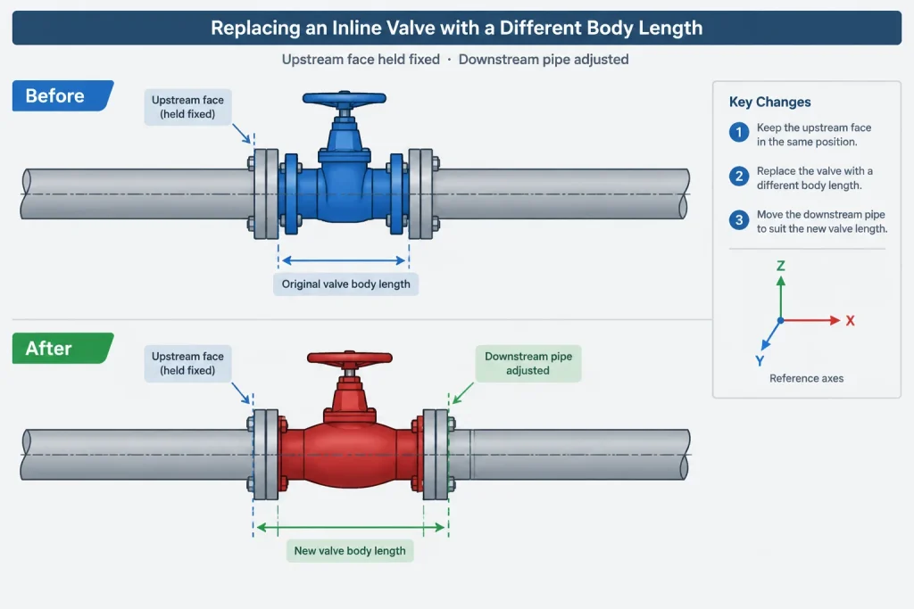
An origin at one connection face can preserve that interface during insertion or replacement. This is useful near equipment nozzles, tie-in points, and other fixed boundaries. The opposite end then moves when the component length changes.
Theoretical-intersection origins
Elbows, tees, and similar fittings may be conveniently controlled from theoretical centerline intersections. This supports routing and fitting takeoff calculations, but the origin must not be mistaken for a physical cut point or connection face.
A library should adopt deliberate conventions by component category and record them in its authoring guidance. Consistency is generally more valuable than forcing every component to use the same origin style.
Why Component Replacement Can Move a Pipeline
Replacement tools or manual block substitutions typically align components using some combination of origin, ports, centerline, and orientation. If the old and new components use different reference conventions, the replacement may introduce a positional shift even when both objects are individually accurate.
For example, replacing a center-origin valve with a face-origin valve can preserve the insertion coordinate but move both physical connections. Similarly, replacing an elbow whose origin is at the theoretical intersection with one whose origin is at an end can change the adjoining straight lengths.
Before replacing a component, determine what must remain fixed:
- The upstream connection face
- The downstream connection face
- The component center
- The equipment-nozzle interface
- The branch intersection
- A support, operator, or maintenance-clearance location
When a replacement has a different controlling dimension, not every point can remain unchanged. The designer must choose the governing interface and then review the affected pipe, supports, clearances, and dimensions.
A Practical CAD Library Check
Component geometry should be validated before it is released for routine project use. A useful check does not require approving the component for engineering service; it verifies that the digital definition behaves consistently with its documented purpose.
- Display local axes. Confirm that the origin and primary axes follow the library convention.
- Identify every port. Check its location, direction, size designation, and connection category.
- Compare ports with reference planes. Make sure mating-face or weld-end ports coincide with the intended dimensional boundaries.
- Connect test pipe or mating components. Look for unexplained gaps, overlaps, offsets, or reversed directions.
- Rotate the component. Confirm that stems, branches, eccentric features, and operators follow the expected local orientation.
- Test replacement. Substitute another valid size or type and observe which reference remains fixed.
- Generate a drawing view. Check that centerlines, dimensions, and joint locations reflect the model definition.
- Compare against verified source data. Do not rely on visual similarity or an unverified generic model.
Drafting Simplifications Still Need Controlled References
Not every project uses intelligent piping objects. Two-dimensional details, neutral-format solids, and conventional CAD blocks may not carry formal port data. The same principles can still be applied by defining documented insertion points, centerlines, end planes, and rotation conventions.
For a reusable block, place geometry on a consistent local coordinate system and include construction references where appropriate. Avoid arbitrary origins far from the object. A distant origin makes rotation, mirroring, copying, and coordinate checks unnecessarily difficult.
When sharing a component, document whether its insertion point represents a face, center, centerline intersection, or another reference. Users should not have to infer the controlling point from the graphics.
Connection-Point Control Is Part of Dimensional Control
Piping CAD connection points are not merely software metadata. They connect dimensional data to model behavior. Correct port locations help preserve joint boundaries, pipe cut lengths, fitting relationships, and equipment interfaces. Logical origins and orientation axes make components easier to place and safer to replace.
A visually detailed model cannot compensate for incorrect references. Before trusting a component in layout or drawing production, verify where it connects, which way it points, what plane controls its dimensions, and what remains fixed when it changes.
Applying Connection-Point Control in a Project Workflow
Connection behavior should be reviewed as part of CAD library governance, not left for designers to discover during routing or drawing production. Component records should identify the controlling origin convention, the meaning of each port, the local orientation reference, and the interface expected to remain fixed during replacement.
Project teams should also distinguish between geometric validation and engineering approval. A component may connect and rotate correctly while still requiring confirmation of its dimensions, end preparation, material definition, specification compatibility, and manufacturer-specific requirements.
Replacement review questions
- Which physical or theoretical reference is being preserved?
- Do the original and replacement components use equivalent port conventions?
- Will a changed component length alter adjoining pipe or joint locations?
- Does the local up direction preserve operator, branch, or eccentric-feature orientation?
- Are equipment interfaces, supports, access areas, and drawing dimensions affected?
- Does the resulting model still agree with the verified component data?
Library documentation priorities
A useful library note should describe references in functional terms. For example, it should state whether an origin represents a mating face, a component center, or a theoretical centerline intersection. It should also identify how port direction and local orientation are interpreted by the authoring system.
Clear documentation reduces dependence on visual inspection and makes behavior easier to compare across fittings, valves, flanges, and equipment connections. When neutral-format geometry or basic blocks are exchanged, the same information can be supplied as accompanying drafting guidance.
Final Verification Principle
Never treat successful snapping as proof that a component is dimensionally correct. Verify the connection boundary, direction, centerline relationship, and controlling reference against approved source data. After replacement or reorientation, review the affected run as a connected assembly rather than checking the edited object alone.
Frequently Asked Questions
What is a piping CAD connection point?
It is a controlled reference that identifies where a pipe, fitting, valve, flange, nozzle, or other object connects. In an intelligent model, it may also carry direction, size designation, connection category, and orientation information.
Is a component origin the same as a connection port?
Not necessarily. The origin controls insertion and transformation, while a port represents an intended connection boundary. A component may have a central or theoretical origin with ports located at its physical ends.
Why can a replacement component shift connected piping?
A shift can occur when the original and replacement objects use different origin, port, or reference-plane conventions. Preserving the same insertion coordinate does not guarantee that their physical connection faces will coincide.
Why is a port direction needed?
The port location identifies where a connection occurs, but its direction establishes the connected run axis. Direction data helps the CAD system align components and distinguish opposing, branch, or angled connections.
What controls the roll of a valve or fitting?
A secondary orientation reference, often expressed as a local up direction or orientation axis, controls rotation around the port axis. This reference affects asymmetric features such as operators, branches, covers, and eccentric geometry.
Can basic CAD blocks use the same principles?
Yes. Even without intelligent port data, blocks can use consistent insertion points, centerlines, end planes, and rotation conventions. These references should be documented so users do not have to infer them from visible geometry.