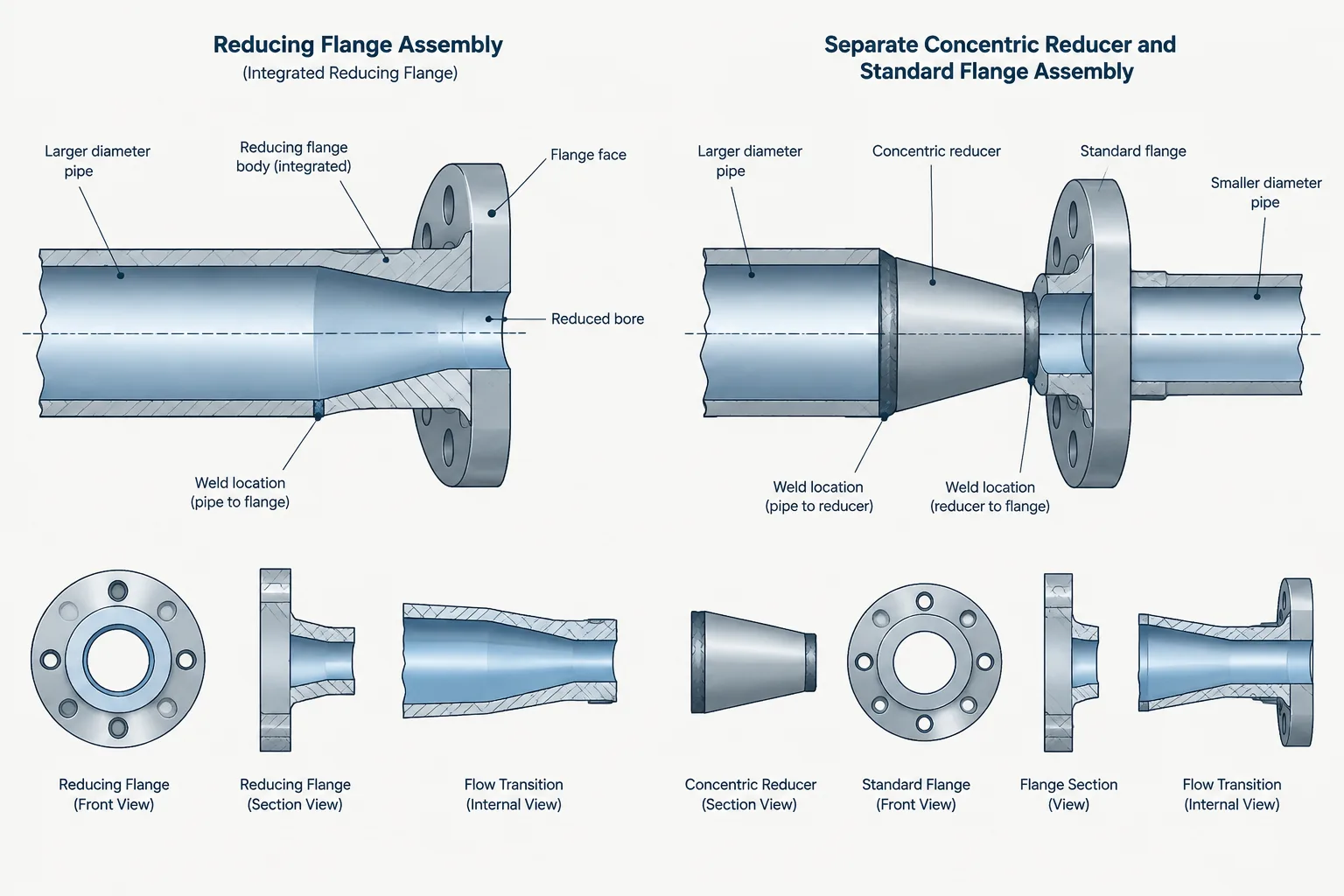
Reducing flanges and separate reducer-and-flange assemblies can connect different nominal pipe sizes, but they place the transition at different points and create different mating interfaces. For CAD users, the key question is not whether the centerlines appear connected. The model must also represent the correct flange drilling, pipe-side connection, bore basis, transition geometry, and component description.
This guide compares the arrangements from a practical layout and model-management perspective. It explains what to verify at equipment nozzles, valves, existing tie-ins, and other locations where an apparently minor size change can affect bolting, alignment, fabrication, access, and the bill of materials.
A reducing flange and a pipe reducer can both connect different nominal pipe sizes, but they do not create the same assembly. The difference affects flange drilling, flow-path geometry, pipe cut length, weld locations, maintenance access, and the data required in a CAD model.
The compact appearance of a reducing flange can make it attractive where space is limited. That does not mean it can automatically replace a reducer followed by a standard flange. Designers must confirm the available component type, permitted size combination, end connection, bore, pressure class, facing, material, and project specification before using either arrangement.
What Is a Reducing Flange?
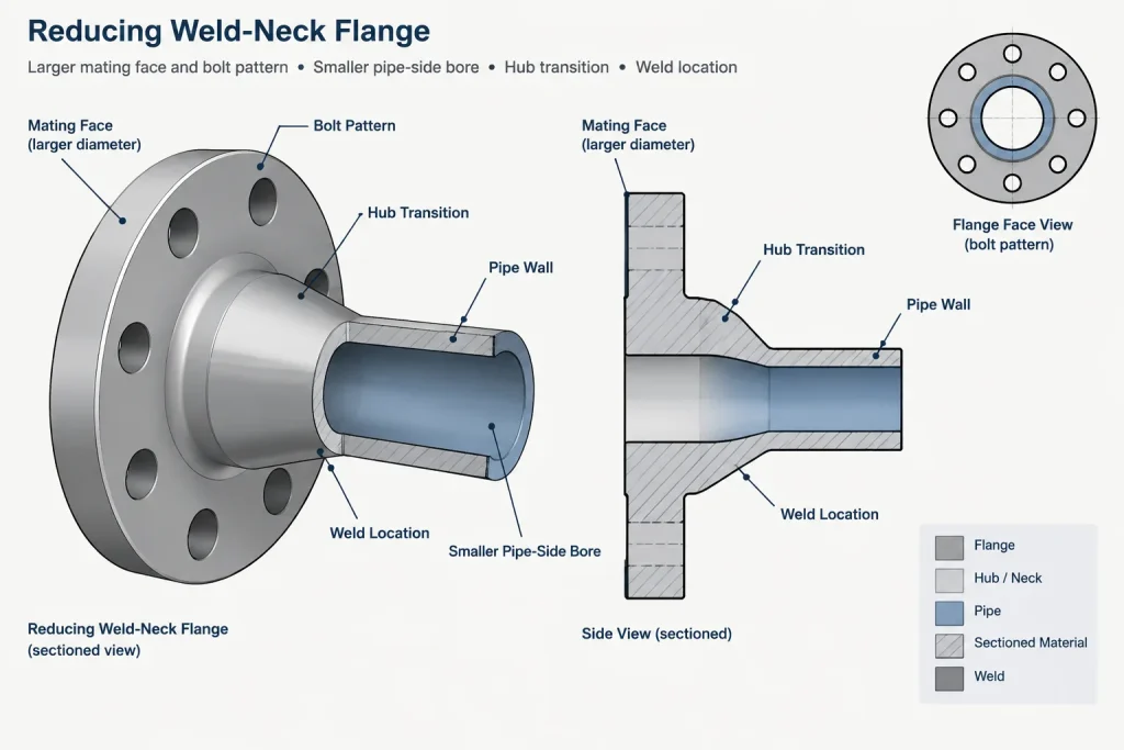
A reducing flange combines two functions in one component: it presents a flange connection associated with one nominal size while connecting to a smaller pipe size on the other side. The flange outside geometry and bolt pattern are generally selected to mate with the larger flanged connection, while the pipe-side opening and attachment details correspond to the smaller pipe.
This creates an important documentation issue. A reducing flange cannot be identified adequately by a single nominal size. Its description should communicate both the mating flange size and the connected pipe size, along with the flange type and other required attributes.
Reducing flanges may be supplied in different end configurations, depending on the product range and project requirements. The pipe side might use a welded, socket, threaded, or other defined connection. The phrase reducing flange alone does not establish how the smaller pipe attaches.
How a Reducer-and-Flange Assembly Differs
A conventional alternative uses a separate pipe reducer and a standard flange sized for the smaller pipe. Starting from the larger side, the assembly usually includes a reducer, a length of smaller pipe when required, and a flange that mates with another small-size flange.
This arrangement places the size transition upstream of the flanged joint. As a result, both halves of the joint normally use the smaller flange size and its corresponding bolt pattern. With a reducing flange, the transition occurs within or immediately behind the flange component, so the joint itself retains the larger mating pattern.
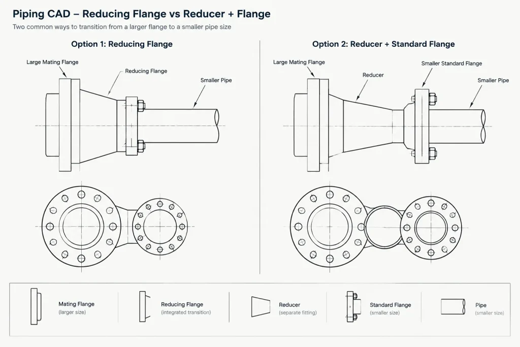
The distinction is especially important at equipment nozzles, valves, strainers, instruments, and existing tie-ins. A model can show connected centerlines while still having an incorrect mating flange outside diameter, bolt circle, bore, or facing.
Reducing Flange vs. Reducer and Standard Flange
| Design consideration | Reducing flange | Reducer plus standard flange |
|---|---|---|
| Location of size transition | Within or directly behind the flange component | In a separate fitting before the flange |
| Mating bolt pattern | Associated with the larger flanged interface | Associated with the smaller flange size |
| Overall assembly length | Often more compact, subject to verified dimensions | Includes the reducer and any required connecting pipe |
| Flow transition | Usually comparatively abrupt | Can use a defined concentric or eccentric reducer geometry |
| Offset capability | Normally maintains a common centerline | An eccentric reducer can shift the smaller pipe centerline |
| Component availability | May be limited by type, size combination, class, material, and supplier | Uses separate components that may be more broadly standardized or stocked |
| CAD data needed | Both nominal sizes, flange geometry, bore, hub, and pipe-side connection | Reducer dimensions, flange dimensions, connecting pipe, and weld locations |
The Bolt Pattern Belongs to the Mating Interface
One of the most common modeling errors is to place a large outside-diameter flange shape in the model but assign it the bolt pattern of the smaller pipe size. The visible flange body does not determine the drilling by itself. The drilling must match the component on the opposite side of the joint.
For example, when a reducing flange is used at a larger equipment nozzle, its flange face, outside diameter, drilling, and facing must be compatible with that nozzle. The smaller pipe size applies to the outlet bore and pipe connection, not to the mating bolt pattern.
A reducer followed by a smaller standard flange produces a different interface. It cannot mate directly with the original larger nozzle without another transition or adapter because the joint dimensions no longer correspond.
Bore and Pipe Wall Require Separate Verification
Nominal sizes do not completely define the internal geometry. The small end of the transition must be checked against the selected pipe outside diameter and wall designation. For a weld-neck configuration, the flange bore and hub detail may need to match the pipe bore or satisfy a project-defined internal transition requirement.
A generic library component should not assume that every pipe schedule uses the same flange bore. Even where the external flange geometry remains unchanged, bore preparation can vary with the connected pipe wall, purchasing description, or manufacturer offering.
CAD metadata should therefore distinguish the flange’s mating size from its pipe connection size and bore basis. Treating the smaller size as a visual label only can lead to an incorrect material description or fabrication detail.
Flow and Layout Considerations
Abrupt versus gradual transition
A reducing flange provides a compact transition, but compact geometry may produce a more abrupt change in flow area than a separate reducer. Whether that matters depends on the service, velocity, equipment requirements, and engineering analysis. The CAD designer should not assume that saving axial space is the only design criterion.
Concentric versus eccentric routing
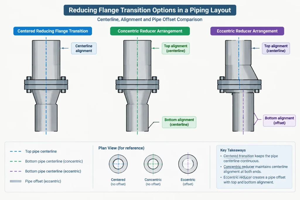
A reducing flange normally keeps the smaller connection centered on the larger flange. A separate eccentric reducer can maintain a selected top, bottom, or side alignment. This may be important for drainage, vapor-pocket control, pump suction arrangements, rack elevations, or connection to an existing pipe centerline.
If an eccentric transition is required, replacing it with a centered reducing flange changes the piping geometry even if the nominal end sizes remain the same.
Valve and equipment access
The shorter assembly can improve clearance in congested areas, but it may also bring the smaller pipe, weld, insulation, or support hardware closer to the equipment. Check access to flange fasteners, gasket removal space, weld inspection areas, nearby drains, and removable equipment components.
How to Represent a Reducing Flange in CAD
A useful reducing-flange model should communicate more than a flange disk with a small pipe attached. Depending on the model’s level of detail, it should include or store:
- The nominal size of the mating flange interface.
- The nominal size of the connected pipe.
- The flange type, pressure class, facing, and material specification.
- The correct outside geometry and bolt pattern for the mating side.
- The verified pipe-side end connection.
- The relevant bore or wall-matching requirement.
- The face-to-end or face-to-weld reference dimension from controlled data.
- A clear insertion point at the flange face or another documented reference plane.
- Port definitions that prevent automatic connection to an incompatible flange size.
In a catalog-driven system, the two ports may need different nominal-size properties. The flange-face port represents the larger mating interface, while the pipe-side port represents the smaller line size. Assigning the smaller size to both ports can allow an invalid connection or generate an incorrect bill of materials.
Drawing and Material List Identification
On an isometric or material list, avoid descriptions that state only “flange” and one size. A clear item description should identify that the component is reducing and show both relevant nominal sizes according to the project’s naming convention.
The documentation should also identify the actual flange form. A reducing weld-neck component is not interchangeable with a reducing slip-on, socket, or threaded configuration merely because the two nominal sizes match. End preparation and installation requirements differ.
Where supplier nomenclature varies, use the project’s approved commodity code and purchasing description rather than relying on an abbreviated CAD family name. The 3D model, isometric, bill of materials, and procurement data should all refer to the same physical item.
Common CAD and Specification Mistakes
- Using a scaled standard flange: Scaling changes every geometric feature together and does not create the required combination of large flange drilling and small pipe connection.
- Assigning only one nominal size: This hides the defining feature of the component and can corrupt connection checks.
- Matching the bolt pattern to the small pipe: The drilling must match the opposite flange at the joint.
- Ignoring the pipe wall: The connected pipe schedule or wall selection can affect the bore and weld transition.
- Replacing an eccentric reducer: A centered reducing flange may change top, bottom, or side alignment.
- Assuming catalog availability: A desired size combination, material, class, facing, and end type may not exist as a standard stocked component.
- Using unverified generic length: Face-to-end and hub dimensions should come from the governing dimensional source or approved manufacturer data.
A Practical Selection and Review Workflow
- Identify the required mating interface. Confirm the nominal size, flange class, facing, and drilling of the nozzle, valve, or existing flange.
- Identify the outgoing pipe. Confirm its nominal size, wall designation, material, and end connection.
- Determine the required transition behavior. Decide whether the line must remain concentric or maintain a top, bottom, or side alignment.
- Check the piping specification. Verify whether a reducing flange is permitted and whether an approved commodity is available.
- Obtain controlled dimensions. Use the applicable dimensional basis and approved manufacturer information where product-specific geometry is required.
- Model both ports correctly. Assign the large flange interface and small pipe connection independently.
- Review clearance and fabrication. Check bolting access, weld access, insulation, supports, drainage, and equipment-removal needs.
- Validate deliverables. Confirm that the isometric description, material list, connection data, and model geometry agree.
Choosing Between the Two Arrangements
A reducing flange is most useful when the larger flange interface must be retained while the outgoing piping changes immediately to a smaller size. It can reduce axial space and component count, provided the exact configuration is permitted and available.
A separate reducer and standard flange offers more control over transition geometry and centerline alignment. It may also be easier to specify from commonly used component families, although it generally requires more space and additional fabrication joints.
The correct choice is not simply the shortest model. It is the arrangement that matches the required flange interface, flow transition, alignment, piping specification, fabrication method, and maintenance needs. Keeping those functions distinct in CAD prevents a nominally connected model from becoming an incompatible field assembly.
Interface-First Model Review
A reliable review starts at the physical joint and works outward. First identify the flange face that must mate with the nozzle, valve, or adjacent component. Then verify the outgoing pipe connection and the geometry used to create the size transition. This approach helps prevent the smaller line size from being applied incorrectly to the flange-face port.
Model reviewers should compare geometry, connection properties, and material data rather than checking only the rendered shape. A visually convincing component can still carry the wrong nominal-size pairing, flange form, facing, bore basis, or end connection.
Questions for a CAD coordination review
- Does the flange-face port match the component on the opposite side of the joint?
- Is the smaller pipe connection stored separately from the mating flange size?
- Does the selected arrangement preserve the required centerline or offset alignment?
- Are the transition component, connecting pipe, welds, and flange represented consistently in the model and material list?
- Has clearance been reviewed using the actual assembly arrangement rather than a schematic placeholder?
- Can the component description distinguish a reducing flange from a separate reducer-and-flange assembly?
- Are product-dependent dimensions controlled by approved project or manufacturer data?
Why the Distinction Matters During Handoff
The model, isometric, material list, and purchasing description should identify the same assembly. If the model uses a single reducing-flange object while the material list calls for a reducer and standard flange, fabrication lengths, weld locations, and connection details may no longer agree.
Temporary CAD placeholders should therefore be marked clearly and replaced before deliverables are issued. Any final selection must be checked against the project piping specification, the required mating component, and controlled dimensional information. A connected model is not proof that the represented parts can be assembled correctly.
Frequently Asked Questions
Is a reducing flange the same as a reducer attached to a flange?
No. A reducing flange combines the larger mating interface and smaller pipe connection in one component. A separate assembly places the size transition in a reducer and uses another flange at the joint.
Which size controls the reducing flange bolt pattern?
The bolt pattern must correspond to the mating flange interface. The smaller nominal size identifies the pipe-side connection and does not by itself define the drilling at the joint.
Can a standard flange be scaled to create a reducing flange model?
No. Uniform scaling changes all geometry together and does not preserve the required relationship between the mating flange geometry and the smaller pipe connection. Use verified component data instead.
Can a reducing flange replace an eccentric reducer?
Not when the eccentric geometry is needed to maintain a selected top, bottom, or side alignment. A centered reducing flange changes that routing condition even if the end sizes appear compatible.
What properties should a reducing-flange CAD object contain?
It should distinguish the mating flange size from the connected pipe size and identify the flange type, class, facing, material, end connection, bore basis, insertion reference, and controlled dimensional source required by the project.
Why can a CAD connection pass while the assembly remains incorrect?
Connection rules may check only selected port properties or centerline compatibility. They may not detect an incorrect bolt pattern, facing, bore, wall match, commodity description, or physical clearance unless those attributes are modeled and validated.