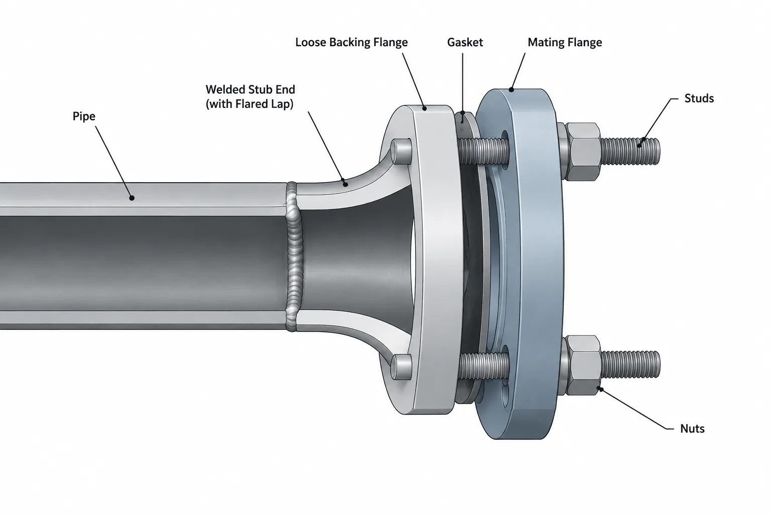
Lap joint flange and stub end CAD models must represent an assembly rather than a conventional one-piece flange. The stub end controls the process bore, welded connection, and sealing plane, while the loose backing flange provides the bolt pattern and transfers clamping force to the lap.
This distinction affects connection points, pipe cut-length references, bolt-hole orientation, installation access, and material takeoff. The following guidance explains how to preserve those functional relationships without assuming that visually similar flange components are interchangeable.
A lap joint connection uses two cooperating components: a stub end attached to the pipe and a loose backing flange positioned behind the stub end’s lap. Treating the pair as an ordinary one-piece flange can create errors in component selection, face location, material takeoff, and fabrication documentation.
The arrangement is especially important in CAD because the flange can rotate independently of the pipe while the stub end establishes the process bore and sealing face. A useful model therefore needs more than the correct outside silhouette. It must represent the functional relationship among the pipe, stub end, backing flange, gasket, and mating component.
How a lap joint assembly works
The stub end is normally joined to the pipe, commonly by a butt weld in metallic piping systems. Its flared lap provides a face for the gasket and a shoulder against which the loose flange applies bolt load. The backing flange slides over the pipe or stub-end neck and remains free to rotate before the joint is tightened.
Unlike a weld neck flange, the backing flange does not have a hub that is butt-welded directly into the process line. Unlike a slip-on flange, it is not normally attached to the pipe with fillet welds. The backing flange transfers bolting force to the stub-end lap rather than becoming a welded pressure-boundary continuation of the pipe.
Under normal service conditions, the stub end provides the wetted bore and sealing surface. The backing flange is generally outside the normal process-wetted boundary. This separation can influence material selection, but it does not justify choosing the backing flange independently of the piping specification, service conditions, corrosion environment, or project requirements.
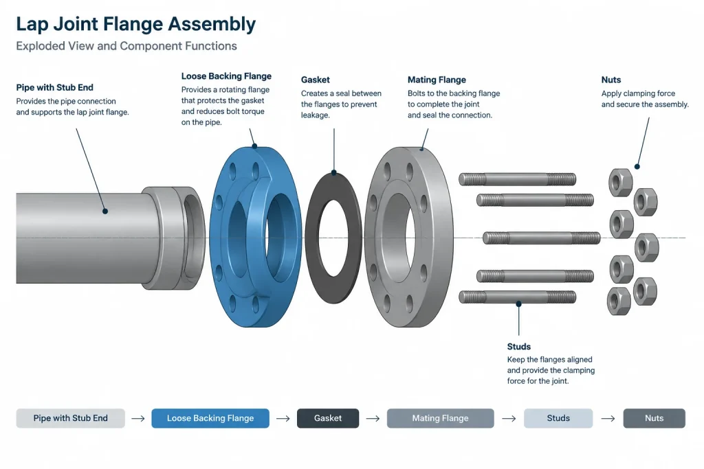
Stub end, backing flange, and gasket functions
| Item | Primary function | Important CAD control |
|---|---|---|
| Stub end | Continues the process bore, connects to the pipe, and provides the lap face | Bore, neck, weld end, lap geometry, and sealing-face plane |
| Lap joint flange | Provides the bolt circle and transfers bolt load to the back of the lap | Class, outside envelope, bore clearance, bolt pattern, and rotational freedom |
| Gasket | Seals between the stub-end lap face and the mating sealing face | Inside and outside envelope, thickness, and seating location |
| Mating flange or assembly | Completes the bolted joint | Compatible facing, drilling, rating basis, and face location |
The flange and stub end must be checked as a compatible pair. Matching only nominal pipe size is insufficient. The applicable dimensional standard, pressure class or rating designation, bore relationship, lap radius, facing arrangement, material specification, and project piping class may all affect compatibility.
The sealing plane is on the stub end
For layout purposes, the most important distinction is that the joint’s sealing plane is established by the stub-end lap face. The loose flange sits behind the lap and supplies clamping force. A CAD component that places its connection port on an arbitrary surface of the backing flange can produce an incorrect face-to-face dimension.
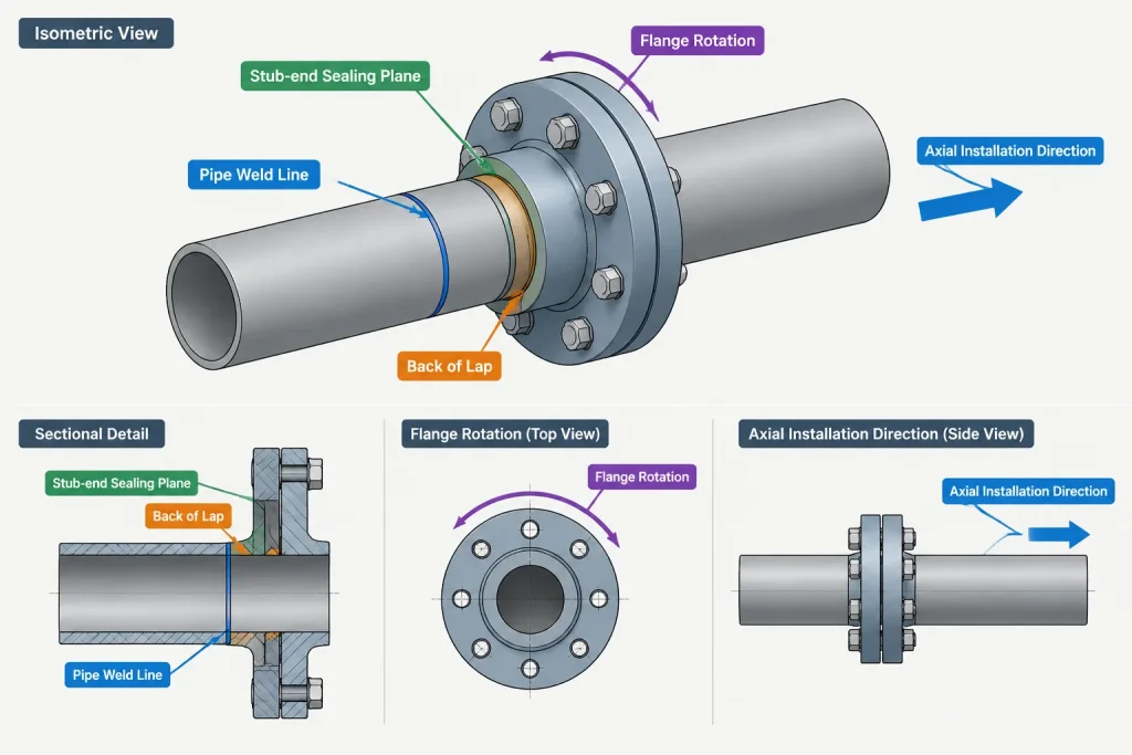
The model should identify at least three different axial references:
- Stub-end sealing plane: the plane against which the gasket is seated.
- Back of lap: the surface that receives load from the backing flange.
- Pipe weld line: the circumferential joint between the stub-end neck and connecting pipe.
These planes are not interchangeable. Pipe cut length is usually controlled from the weld line or another fabrication reference, while equipment layout is often controlled from the sealing plane. The backing flange thickness affects the bolted-joint envelope and bolting requirements, but it should not replace the stub-end face as the piping connection datum.
Why flange rotation matters
Because the backing flange is loose before tightening, its bolt holes can be rotated without rotating the welded pipe or stub end. This can simplify bolt-hole alignment during assembly, particularly where the pipe material is difficult to rotate or where field alignment is important.
Rotational freedom should not be confused with unlimited adjustability. The flange still has to move axially into its assembled position, fit over the stub-end neck, bear correctly against the lap, and align with the mating bolt pattern. Nearby elbows, supports, insulation, welds, or equipment can obstruct flange installation or rotation.
In a CAD model, the bolt pattern can be represented parametrically or by a simplified bolt-circle reference. If individual holes are modeled, their orientation should remain editable until project requirements establish the final clocking. A designer should not lock the flange orientation merely because a library component was inserted with a default rotation.
Lap joint flange versus slip-on flange
The two flange types can look similar in simplified views, but they perform different jobs. A slip-on flange fits over the pipe and is attached by welding. A lap joint flange remains loose and has internal geometry intended to clear and bear against the stub-end lap assembly.
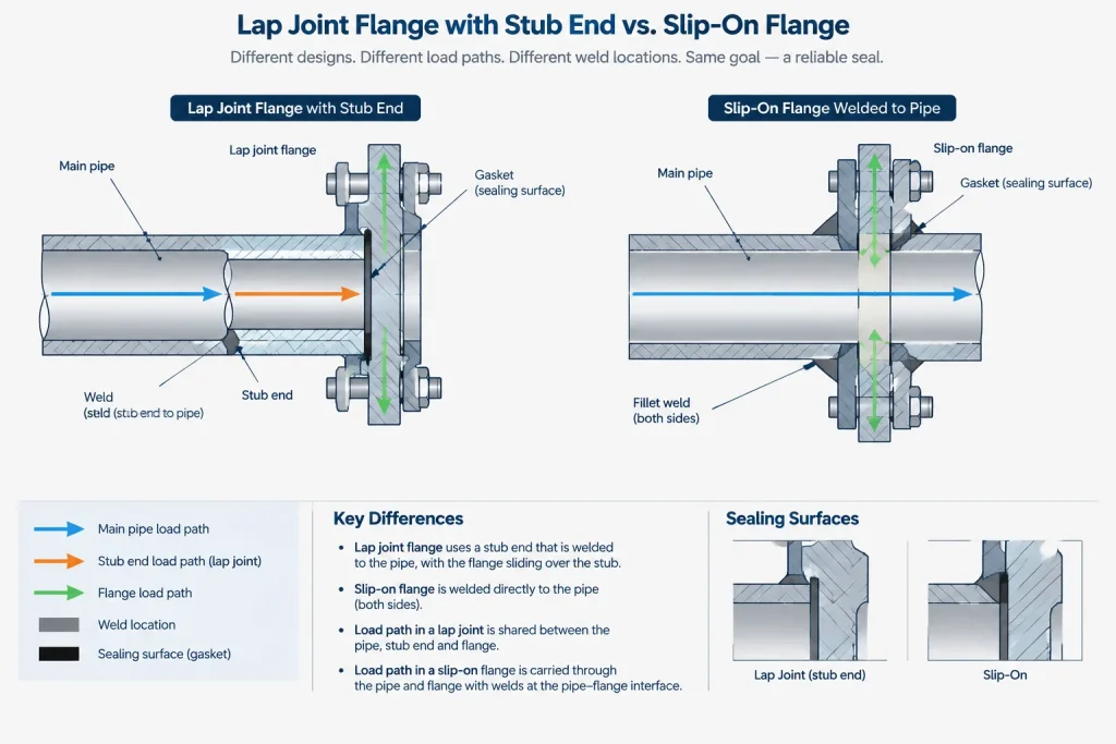
Substituting a generic slip-on flange model can hide several problems:
- The bore or internal corner may not represent clearance for the stub-end neck and lap radius.
- The model may incorrectly show flange-to-pipe welds.
- The connection point may be placed on the flange instead of the stub-end sealing face.
- The bill of materials may omit the stub end or count the pair as one purchased item.
- The drawing may imply that the flange is fixed against rotation.
Visual similarity is therefore not a reliable basis for CAD substitution or purchasing.
Dimension control in a piping model
A lap joint assembly should be built from verified component dimensions rather than inferred from a flange silhouette. Dimensions may vary with the governing standard, product form, size, class, wall relationship, facing, and manufacturer.
Control the welded piping geometry
Locate the stub-end weld line and sealing plane from verified data. The distance between these references affects the straight-pipe cut length and the overall position of the joint. Where a stub end must match a particular pipe wall, confirm the intended bore transition and end preparation rather than assuming that every nominally matching component has identical geometry.
Control the joint stack-up
The assembled connection includes both sealing faces and the gasket between them. The model or drawing workflow should state whether gasket thickness is represented explicitly, included in a controlled joint gap, or handled by a project convention. Mixing these methods can shift connected equipment or spool endpoints.
Control the external envelope
Model enough flange, bolt, nut, and tool-clearance geometry to perform the required layout checks. The loose flange may need room to slide and rotate during fabrication or installation. An assembly that fits in its final position may still be impossible to install if the backing flange cannot pass an adjacent feature.
Materials and piping specification considerations
One practical advantage of the arrangement is that the wetted stub end and the external backing flange may serve different material roles. In some specifications, this permits a corrosion-resistant wetted component to be paired with a different backing-flange material. However, this is a specification decision, not a default CAD assumption.
The designer must also consider the external environment, material compatibility, temperature, bolting system, applicable code, and procurement rules. The backing flange still carries mechanical load, and leakage can expose surfaces that are not normally wetted. Material descriptions in the model and bill of materials should identify each component separately.
BOM and drawing documentation
A lap joint connection usually needs separate records for the stub end and backing flange. Depending on the project workflow, the gasket and bolting may also be separate line items or part of a joint-management system.
Useful documentation fields include:
- Nominal pipe size and associated pipe wall or bore requirement
- Stub-end material, type, end preparation, and dimensional basis
- Backing-flange material, class or rating designation, and dimensional basis
- Facing and gasket description
- Bolt pattern orientation where orientation is controlled
- Weld identification and inspection requirements where applicable
On an isometric, show the stub end as the welded component and the flange as the loose backing member when the drawing detail level permits. Avoid weld symbols that imply the flange itself is welded to the pipe. Notes should also avoid ambiguous descriptions such as “loose flange” unless the project specification clearly defines the intended assembly.
Practical CAD review checklist
- Confirm that both the stub end and backing flange are present in the model and material takeoff.
- Place the connection port on the verified stub-end sealing plane.
- Locate the pipe weld line from verified stub-end geometry.
- Check compatibility among the flange bore, stub-end neck, lap, and internal flange radius.
- Keep bolt-hole rotation editable unless clocking is specifically controlled.
- Check axial installation access as well as the final operating envelope.
- Represent the gasket and joint gap according to one consistent project convention.
- Do not infer dimensions or compatibility from a slip-on flange block.
- Verify material assignments for the wetted stub end and the backing flange separately.
- Use approved project and manufacturer data before releasing fabrication dimensions.
A reliable lap joint flange model makes the assembly’s load path and reference planes clear. When the stub end controls the bore and sealing face, the flange controls bolting, and each item remains separately documented, CAD geometry can support accurate layout without concealing the checks still required for specification and fabrication.
Organizing the assembly in a CAD library
A practical component library can treat the stub end and backing flange as related parts within one managed assembly while retaining their separate identities. This allows the model to move as a coordinated connection without hiding the differences in geometry, material, fabrication, and procurement.
The assembly definition should distinguish the process connection datum from the flange body origin. The process connection belongs at the verified stub-end sealing plane. Separate reference geometry can identify the weld line, back of lap, gasket location, bolt pattern, and backing-flange envelope.
Preserve independent component data
- Stub end: Assign the pipe connection, bore relationship, sealing face, weld information, and wetted-material description.
- Backing flange: Assign the drilling, external envelope, clearance geometry, rating designation, and independent material description.
- Gasket and bolting: Manage these according to the project joint convention rather than embedding unverified assumptions in the flange geometry.
This structure helps prevent a visually complete model from producing an incomplete material takeoff. It also makes component replacement safer because a revision to the backing flange does not automatically redefine the stub-end weld or sealing plane.
Model validation before drawing release
Validation should compare the CAD object with approved project data at the functional interfaces, not merely at its outside profile. Review the bore path, weld-end geometry, lap contact, internal flange clearance, gasket seating location, mating face, and bolt pattern as a connected system.
Interference review should include assembly movement. The backing flange may fit in its final position yet lack enough access to slide over the relevant geometry or rotate for bolt alignment. Nearby piping, equipment, supports, insulation, and structural features can therefore affect constructability even when the completed joint appears clear.
Drawing and data consistency
Isometrics, orthographic drawings, spool records, and bills of material should describe the same component relationship. If the model shows a loose backing flange but the drawing implies flange-to-pipe welds, the documentation is internally inconsistent. Likewise, a material takeoff that lists only a flange can omit the welded stub end that establishes the actual process connection.
Final dimensions, materials, facing details, bolting, and component compatibility must be checked against the governing project specification and approved product data before fabrication or procurement.
Frequently asked questions
Should the CAD connection point be placed on the backing flange?
No. The piping connection datum should normally follow the verified sealing plane on the stub-end lap. The backing flange sits behind the lap and should not replace the sealing face as the axial connection reference.
Can the stub end and flange be stored as one CAD assembly?
Yes, provided the assembly preserves separate component identities, attributes, materials, and bill-of-material records. Grouping parts for placement should not cause them to be treated as one fabricated or purchased item.
Does rotational freedom mean the flange can move during service?
The useful rotational freedom exists before the bolted joint is tightened. It supports bolt-hole alignment during assembly; it should not be interpreted as operating movement in the completed joint.
Why is a slip-on flange block an unsuitable substitute?
A slip-on block can imply the wrong attachment method, internal clearance, connection datum, weld symbols, and material takeoff. Similar outside profiles do not establish functional or dimensional compatibility.
Should gasket thickness be included in the CAD model?
The project should use one controlled convention. The gasket may be modeled explicitly or managed through an established joint-gap method, but mixing conventions can shift connected components and spool endpoints.
What should be checked when replacing a library component?
Recheck the stub-end sealing plane, weld line, bore relationship, lap contact, flange clearance, drilling, external envelope, material assignments, and mating-joint requirements using approved project and product data.