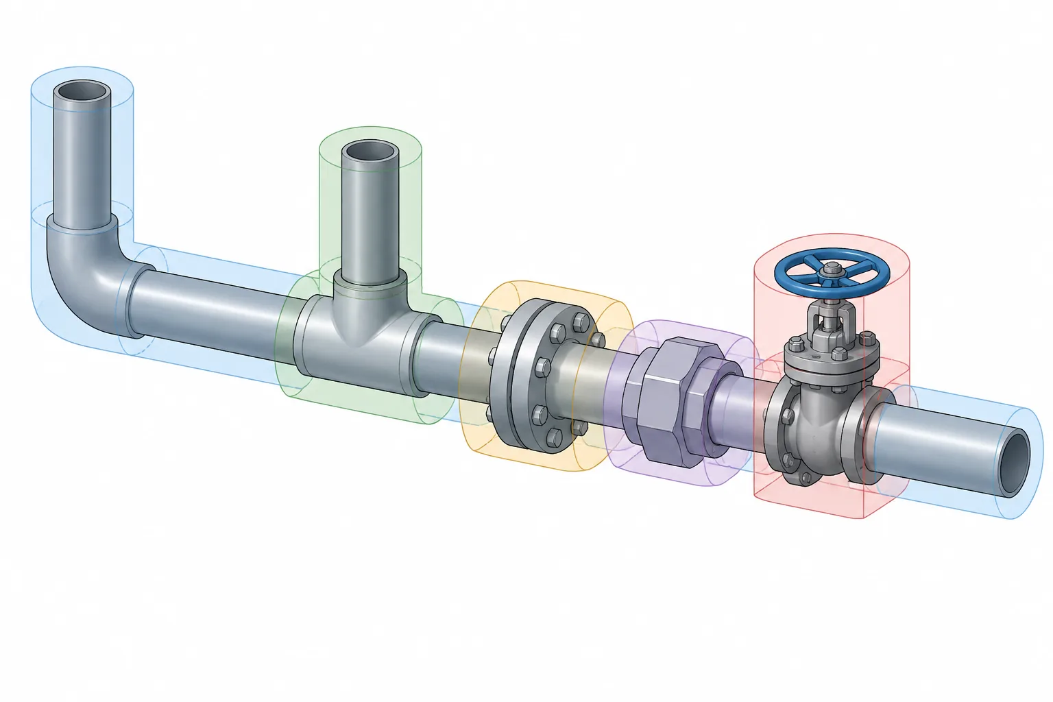
In piping CAD, a correct nominal size does not guarantee a correct physical envelope. Nominal size identifies compatible connections, while the space occupied by a fitting, flange, valve, or joint depends on its actual body geometry and external features.
This guide explains how to distinguish the pipe body from component and service envelopes. It also outlines a practical approach to modeling, clash detection, insulation checks, access reviews, and provisional geometry when verified component dimensions are not yet available.
A nominal pipe size identifies a piping system size, but it does not fully describe the space occupied by every component in that system. Straight pipe has a defined outside diameter for a given nominal size and dimensional system. Elbows, tees, couplings, unions, flanges, valves, and branch fittings can extend well beyond that pipe cylinder.
This distinction matters whenever a designer checks clashes, routes piping near structure, reserves insulation space, locates supports, or creates reusable CAD components. A model that represents every item as a pipe-sized cylinder may look orderly while missing the actual component envelope.
Pipe outside diameter is not a universal component diameter
For straight pipe, outside diameter is a primary geometric property. Within a recognized pipe-size series, changing the schedule generally changes wall thickness and inside diameter rather than the nominal outside diameter. This makes pipe OD a useful basis for routing centerlines, displaying pipe bodies, and creating insulation envelopes.
A fitting, however, is not simply another length of pipe. Its body must accommodate a change in direction, a branch, a transition, a joint mechanism, or an attachment feature. The resulting exterior shape depends on the component type and manufacturing form.
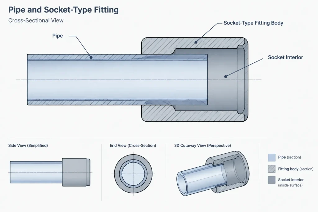
At a compatible butt-weld end, the fitting end is intended to meet the adjoining pipe. Away from that end, the fitting body may have a different profile. Socket-weld, threaded, mechanical, and flanged components can have hubs, bosses, sockets, wrenching surfaces, glands, or bolting that project beyond the pipe OD.
Three different envelopes should not be confused
1. The pipe body envelope
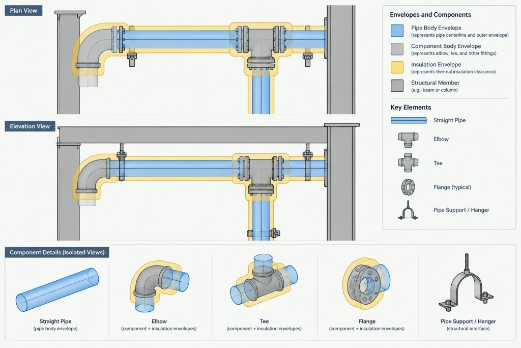
This is the cylinder defined by the pipe outside diameter along a straight run. It is the simplest envelope and often forms the base geometry for piping models.
2. The component body envelope
This is the physical space occupied by the fitting or valve body. It may be circular, tapered, lobed, rectangular, or irregular. An elbow body occupies space around a curved centerline, while a tee includes both a run body and a projecting branch body. A forged fitting may include a compact but relatively heavy section around its sockets or threaded ends.
3. The installation and service envelope
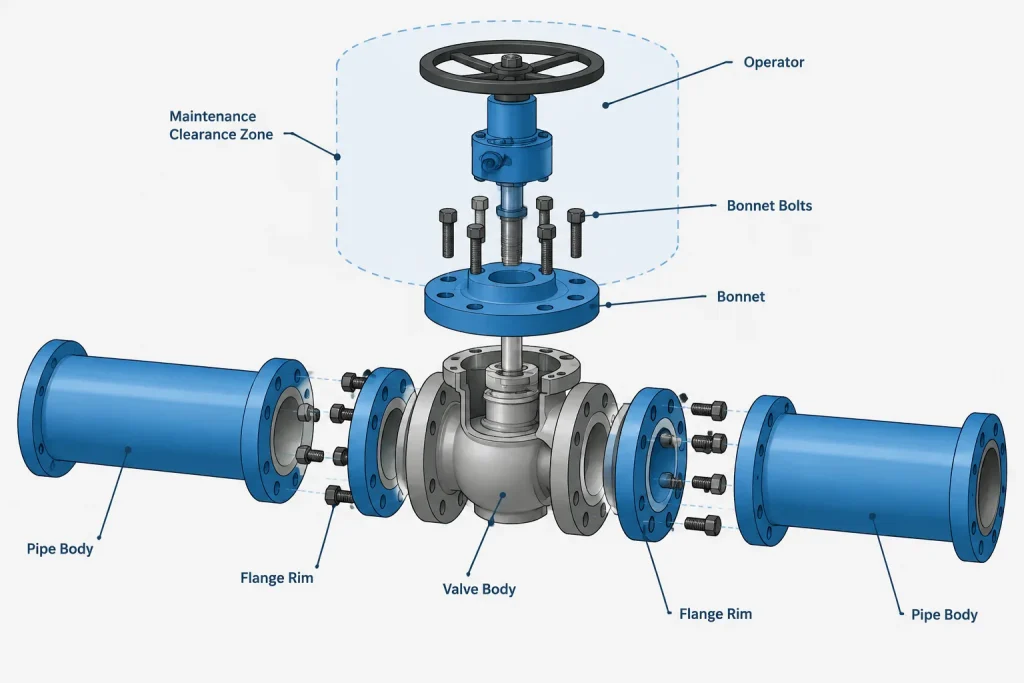
This includes space beyond the static metal body. Examples include insulation, flange studs, valve operators, removable covers, tool access, joint assembly movement, and maintenance withdrawal paths. A component can clear an obstruction physically while still being impossible to install, bolt, operate, or remove.
These envelopes serve different checks. Using one in place of another can produce false confidence during coordination.
Why different component types exceed the pipe OD
| Component type | Why its envelope differs from pipe OD | Important CAD check |
|---|---|---|
| Butt-weld elbow | The curved body sweeps around the centerline and may not be represented adequately by intersecting straight pipe cylinders. | Check the complete swept envelope near steel, walls, and adjacent lines. |
| Tee | The branch intersection creates a body around two centerlines, with material shaped through the crotch region. | Check both run and branch envelopes, especially near parallel piping. |
| Reducer | The exterior transitions between two end sizes rather than following one constant pipe OD. | Use the correct large-end and small-end geometry and the specified orientation. |
| Socket-weld or threaded fitting | The fitting body surrounds the pipe end or internal thread and may include wrenching flats or reinforced sections. | Do not model it as a pipe-size cylinder or scale it from another size. |
| Coupling or union | The joint body surrounds the connected pipe, while a union also includes a separable central assembly. | Allow for the largest body section and any required disassembly movement. |
| Flange | The flange rim, hub, bolts, and nuts extend beyond the pipe body. | Check the flange OD, bolting envelope, wrench access, and joint separation needs. |
| Valve | The pressure-containing body, bonnet, stem, and operator have separate external shapes. | Check body clearance independently from operator and maintenance clearance. |
Nominal size is a selection key, not a bounding dimension
Nominal size helps match compatible piping components, but it should not be used as a measured diameter or as a substitute for component dimensions. Two items assigned to the same nominal pipe size can have very different overall envelopes.
This is especially important in CAD catalogs. A size field may control connection compatibility, ports, and part selection without directly defining the maximum width or height of the component. The geometry may also depend on end connection, pressure designation, material form, manufacturer, or project specification.
Scaling an existing component until its ports appear to match is unreliable. Proportions, center-to-end dimensions, hub geometry, wall transitions, bolt patterns, and operator sizes do not necessarily scale uniformly between nominal sizes or component classes.
Outside dimensions that a CAD component may need
No single dimension describes every fitting envelope. Depending on the component, a controlled CAD representation may require several geometric inputs:
- Connection size and connection type at each port
- Port centerlines and face, weld, socket, or thread reference planes
- Center-to-end, face-to-face, or end-to-end dimensions
- Maximum body width, depth, or diameter
- Hub, boss, gland, bonnet, or operator projections
- Flange rim and bolting envelope
- Reducer large-end and small-end geometry
- Insulation or lining envelope where applicable
- Removal, assembly, operation, and tool-access zones
Not all of these belong in every model. The appropriate detail depends on the purpose of the model and the project phase. A routing model may use a conservative simplified body, while fabrication or vendor coordination may require verified component geometry.
A practical CAD workflow for fitting envelopes
Start with the connection geometry
Define the ports, centerlines, nominal sizes, and end types before creating the exterior body. Connection points should remain stable so that replacing a simplified component with verified geometry does not shift adjoining pipe unexpectedly.
Separate connection data from body geometry
A component can have correct port locations but an inaccurate body envelope. Treat these as separate quality checks. Correct center-to-end dimensions do not prove that the exterior shape is suitable for clash detection.
Identify the source of each critical dimension
Use applicable dimensional references, approved project catalogs, or manufacturer information as required by the component. Generic dimensional data may be appropriate for standardized features, but manufacturer-dependent bodies and operators should not be presented as verified without supporting information.
Use conservative placeholders visibly
When exact dimensions are unavailable, a placeholder envelope can support preliminary routing. It should be identifiable as provisional rather than silently treated as final. A hold, status field, model property, or review note can distinguish assumed geometry from verified geometry.
Check insulation separately
Insulation generally follows the pipe or component exterior, not the piping centerline alone. Around flanges, valves, unions, and irregular fittings, the outer envelope may change or require removable covers. A constant insulation cylinder can therefore understate local space requirements.
Run both clash and access reviews
Hard-clash detection asks whether solid objects overlap. An access review asks whether people can assemble, operate, inspect, or remove the component. The second review often requires temporary or nonphysical clearance objects around bolting, operators, and removable parts.
Common modeling errors
- Using pipe OD for all items: This understates the body size of many fittings, flanges, and valves.
- Checking only a plan view: A component may clear horizontally but interfere vertically because of a bonnet, branch, or operator.
- Ignoring irregular profiles: A single maximum-diameter cylinder can be safe but overly restrictive, while an undersized cylinder can miss a real clash.
- Assuming matching ports mean matching bodies: Components with the same nominal connections may have different exterior dimensions.
- Applying one envelope to every pressure designation or end type: A catalog family may require distinct geometry rather than only different metadata.
- Omitting temporary access space: A joint that fits in operation may not have enough room for installation or removal.
How much geometric detail is enough?
The best model is not necessarily the one with the most surface detail. It is the one that accurately represents the dimensions relevant to the intended decisions.
For early routing, useful geometry usually includes reliable port locations, overall length, and a defensible body envelope. For coordination, flange rims, valve bodies, operators, branches, and insulation may need clearer representation. For fabrication or procurement interfaces, project-approved dimensions and component-specific details become more important.
Small cosmetic features rarely improve layout decisions, but missing a major boss, union nut, flange rim, or valve operator can invalidate a clearance review. Model detail should therefore be driven by dimensional risk rather than appearance.
Key takeaway
Pipe outside diameter describes the straight pipe body; it does not define the maximum outside dimensions of every fitting connected to that pipe. Nominal size establishes compatibility and catalog selection, while the actual component envelope comes from its form, connection type, dimensional basis, and manufacturer or project data where applicable.
Reliable piping CAD separates pipe geometry, component geometry, and installation clearance. That approach produces better clash reviews, more realistic layouts, and fewer surprises when components must be insulated, bolted, operated, or removed in the field.
Applying the envelope concept during model review
Envelope accuracy should be reviewed as a separate model-quality issue rather than inferred from connection accuracy. A component may connect correctly at every port while still being too small, too large, or incorrectly shaped for coordination.
Review the intended use of the geometry
Before accepting a CAD component, identify what the model must support. Routing, spatial coordination, insulation planning, installation sequencing, operation, and maintenance do not always require the same level of detail. The geometry should represent the features that affect the decisions being made.
Record the status of dimensional inputs
CAD libraries benefit from distinguishing verified geometry from generic or provisional envelopes. Useful component properties can identify the dimensional source, approval status, end-connection basis, and whether body, operator, insulation, or maintenance clearances remain subject to confirmation.
Review replacements as dimensional changes
Replacing a generic component with a selected product should trigger another envelope review, even when the nominal size and port locations remain unchanged. Body contours, hubs, bonnets, operators, joint hardware, and removal paths may differ without changing connection compatibility.
Coordinate more than the visible solid
Clearance objects can represent space that is not part of the permanent metal body. Examples include operator movement, bolting access, joint separation, removable covers, and withdrawal paths. Keeping these zones visually distinct prevents them from being mistaken for physical component geometry.
CAD envelope review checklist
- Connections: Confirm that port locations, centerlines, end types, and reference planes match the intended piping definition.
- Body: Check maximum projections in plan, elevation, and around changes in direction.
- Adjacent features: Include hubs, glands, bolting, bonnets, operators, branches, and other significant projections.
- Insulation: Verify that the insulation representation follows the relevant component shape rather than only the straight-pipe cylinder.
- Access: Review assembly, operation, tool use, inspection, and removal independently from hard clashes.
- Data status: Mark assumptions and placeholders so they are not interpreted as approved component geometry.
- Change control: Repeat clearance checks when the component type, end connection, dimensional basis, or selected product changes.
This review structure helps keep nominal-size compatibility, physical geometry, and working clearance from becoming mixed into a single unreliable assumption.
Frequently asked questions
Does nominal pipe size define the outside diameter of a fitting?
No. Nominal size is primarily a selection and compatibility designation. A fitting may connect to pipe of that nominal size while its body, hubs, sockets, branch, or joint features extend beyond the pipe outside diameter.
Can pipe OD be used as a temporary fitting envelope?
It can support limited preliminary routing, but it should be identified as a provisional representation. Using the pipe cylinder as an unmarked final envelope can conceal clashes involving fitting bodies, flange rims, valve operators, unions, or other projections.
Does a component with correct port locations have reliable clash geometry?
Not necessarily. Port geometry controls connectivity, while body geometry controls much of the physical clash behavior. Both need independent review.
Should insulation be modeled as a constant cylinder through fittings and valves?
Not automatically. Irregular components and removable insulation covers may create local envelopes that differ from the straight-run insulation cylinder. The representation should follow the project’s insulation and coordination requirements.
Why is scaling a fitting from another nominal size unreliable?
Component proportions do not necessarily change uniformly. Connections, body transitions, hubs, bolting, center-to-end geometry, and operators may follow different dimensional requirements. Each CAD size should be based on appropriate dimensional information.
What should be checked when a placeholder is replaced?
Recheck the body envelope, external projections, insulation, access zones, and maintenance paths. Matching nominal sizes and connection points do not prove that the replacement occupies the same space.