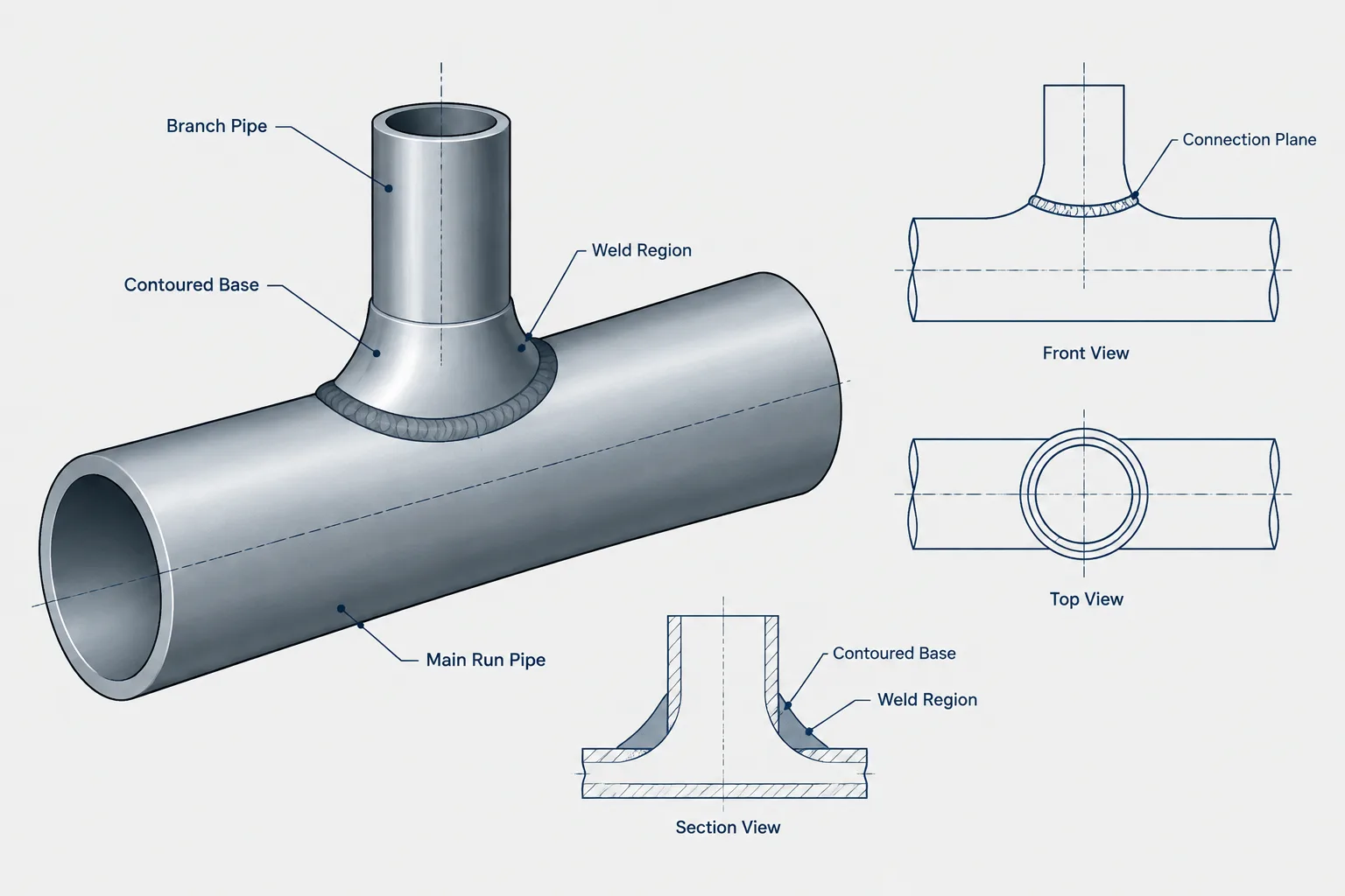
Branch outlet fittings require careful data control because the same general appearance can represent different run interfaces, branch connections, and catalog items. This guide explains how to interpret those properties in piping CAD, place the component from controlled references, and keep the model aligned with drawings and material outputs.
Branch outlet fittings provide a compact way to connect a smaller branch to a larger run pipe. Unlike a tee, an outlet fitting is attached directly to an opening in the run. Its body may provide reinforcement around that opening while also creating the branch connection.
These components can look simple in a piping model, but their definition depends on more than two nominal sizes. The run size, branch size, branch end connection, fitting geometry, material specification, and attachment method all affect selection and documentation. Treating an outlet as a generic cone or scaling one CAD symbol can hide important differences.
What Is a Branch Outlet Fitting?
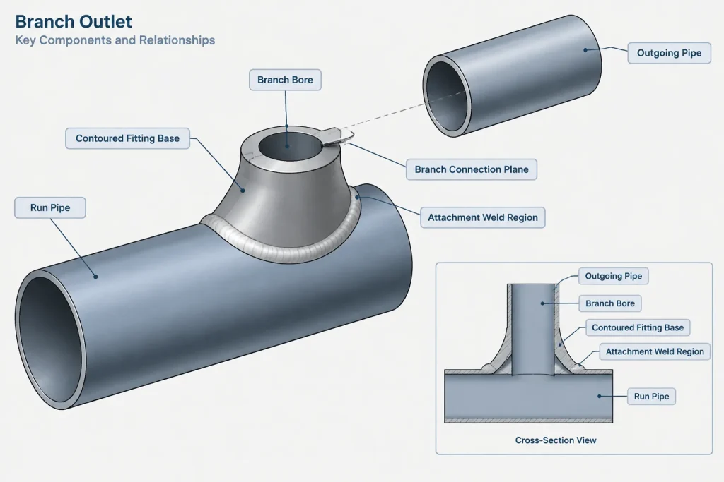
A branch outlet fitting is a manufactured component installed on the outside of a run pipe. Its lower surface is shaped to fit the run, and its upper end provides a connection for the branch pipe, valve, instrument assembly, or another component.
Depending on its design, the outlet may terminate in a butt-weld, socket-weld, or threaded connection. Other specialized configurations exist, so the project piping specification and approved component catalog should control the available choices.
An outlet fitting is not automatically interchangeable with any of the following:
- A reducing tee installed in the run
- A fabricated set-on or set-in branch
- A coupling welded over a drilled opening
- A branch connection with a separate reinforcement pad
- A nozzle or boss supplied as part of equipment
These arrangements can serve similar routing purposes, but their geometry, reinforcement basis, weld details, examination requirements, and material descriptions may differ.
The Two Sizes Describe Different Interfaces
Outlet fittings are generally associated with both a run size and a branch size. The run size identifies the pipe surface that receives the fitting. The branch size identifies the nominal connection leaving the fitting.
This distinction matters in CAD catalogs. A component described only by branch size is incomplete because the contoured base must match the intended run. Two fittings with the same branch connection may require different base geometry when installed on different run sizes.
| Catalog property | What it controls | Common modeling risk |
|---|---|---|
| Run size | Fit of the contoured base to the run outside surface | Using one base shape for several run sizes |
| Branch size | Nominal size of the outgoing connection | Reading the size pair in the wrong order |
| Branch end type | How the branch pipe or component connects | Substituting threaded, socket-weld, and butt-weld variants |
| Body configuration | External envelope, bore transition, and attachment geometry | Scaling a generic solid instead of selecting a catalog item |
| Material and specification | Whether the item is permitted for the piping class | Selecting by geometry alone |
Size descriptions should follow the naming convention established by the project catalog or manufacturer data. If imported data reverses the size order, mapping rules should correct the data rather than relying on designers to interpret inconsistent descriptions.
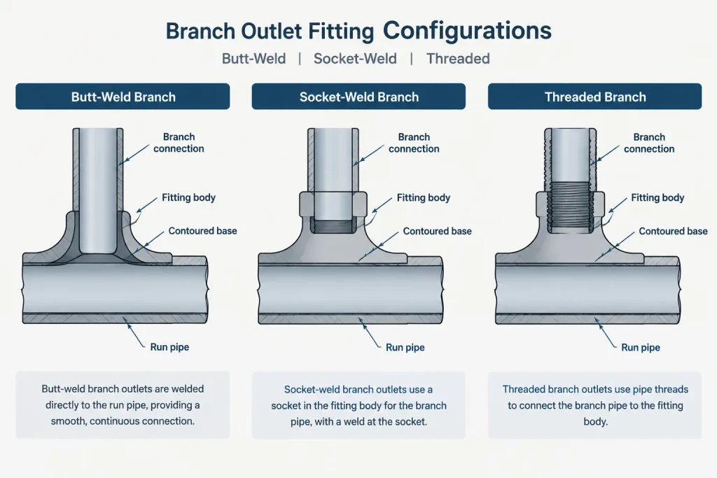
Branch End Types Change the Connection Detail
Butt-weld outlet
A butt-weld outlet presents a weld end for the branch pipe. The relevant model interfaces normally include the branch centerline, outlet end plane, bore, and weld preparation reference. The branch pipe cut length is controlled from the appropriate weld reference, not from the visible top of a simplified body.
Socket-weld outlet
A socket-weld outlet receives the branch pipe inside a socket. The model or catalog definition must distinguish the socket entrance, internal stop, insertion reference, and branch connection point. Pipe cut length should follow the project’s socket-weld assembly method rather than a visual measurement to the outside of the fitting.
Threaded outlet
A threaded outlet receives a mating threaded component. The final assembled position depends on thread engagement and makeup, so the connection should not be treated as a simple face-to-face butt joint. CAD libraries often use a defined connection point for routing while drawings or notes communicate the applicable thread requirements.
The end type also affects the bill of materials. A fitting with the correct size pair but the wrong branch connection is not an acceptable geometric substitute.
Important Geometry in the CAD Model
A useful branch outlet model should contain enough information to support routing, interference review, drawing generation, and material extraction. It does not always need detailed weld preparations or internal machining, but its controlling references should be clear.
Run centerline and radial direction
The fitting is oriented radially from the run pipe. Its branch axis typically intersects the run axis for a conventional perpendicular connection. The CAD placement routine should align the fitting with the run centerline and preserve the intended branch clocking.
Contoured base
The underside of the fitting follows the outside surface of the run. This contour is one reason a branch outlet should not be represented by a universally scaled block. Run outside diameter influences the seating geometry even when the nominal branch size remains unchanged.
Branch connection plane
The outlet end or routing port establishes where the branch pipe begins. This plane is essential for calculating straight-pipe length and locating the next component. Its position must come from verified component data rather than an assumed body height.
Weld and cutout references
The attachment weld, branch opening, and internal bore may be represented differently depending on model detail. A general arrangement model may show only the component envelope, while a fabrication detail may need clearer weld boundaries and opening information. The model should not imply an unverified weld profile simply because a detailed solid is visually possible.
External envelope
The outlet body can project beyond the branch pipe outside diameter. That envelope matters near adjacent branches, insulation, supports, structural steel, and equipment surfaces. A centerline-only symbol may be adequate on a schematic, but physical coordination requires a realistic space claim.
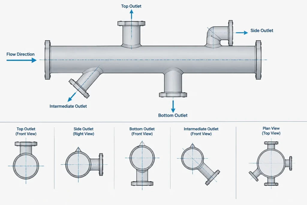
Orientation and Branch Clocking
For a horizontal run, an outlet may be located at the top, bottom, side, or an intermediate clock position. For a vertical run, its direction is normally controlled by plant coordinates or a local equipment reference.
The design model should preserve this orientation as data rather than relying only on appearance. Useful properties include the run identifier, branch identifier, branch direction, fitting tag when required, and connection status.
Clocking becomes especially important when the branch connects to an instrument, drain, vent, valve, or sloped line. A small angular placement error can change elevations and downstream alignment. Isometric extraction should show the branch direction unambiguously using coordinates, dimensions, or established orientation conventions.
Outlet Fitting Takeoff and Pipe Cut Length
The fitting takeoff is the distance from a defined run reference to the branch connection reference. Designers should not derive it from a generic sketch or by measuring the displayed solid unless that solid has been built from verified data.
For branch pipe cut length, identify:
- The outlet’s actual connection plane or engagement reference
- The corresponding reference on the next fitting, valve, or flange
- The connection type at each end
- Any required field-fit or fabrication allowance
- Whether the drawing dimension is to a weld line, fitting face, centerline, or another datum
Changing from one outlet type to another can move the branch connection point even when the nominal sizes do not change. Replacement should therefore trigger a dimensional review of the connected branch.
Specification and Reinforcement Control
The presence of a manufactured outlet fitting does not by itself confirm that a branch connection is acceptable. Component selection must remain consistent with the piping specification and the project’s design basis. Relevant considerations may include material, wall requirements, service limitations, branch geometry, fabrication method, examination, and reinforcement evaluation.
CAD users should avoid inferring engineering approval from a catalog symbol. A component can be modeled accurately and still be unsuitable for a particular service. The approved piping class should determine which outlet families and size combinations are selectable.
A Practical CAD Workflow
-
Confirm the branch type. Determine whether the design requires a manufactured outlet, tee, fabricated branch, or another connection arrangement.
-
Select the run first. Read its nominal size, outside diameter basis, material class, and specification context.
-
Define the branch. Confirm branch size, end connection, direction, and downstream component requirements.
-
Choose an approved catalog item. Filter by both interfaces and by the applicable piping class. Do not select solely by graphical resemblance.
-
Place and orient the fitting. Align it to the run axis and apply the intended branch clocking.
-
Verify connection references. Check that the routing port, weld plane, socket reference, or threaded connection point matches the catalog definition.
-
Review the space claim. Check the fitting body, branch, insulation, weld access, nearby supports, and maintenance needs.
-
Validate deliverables. Confirm the size description, end type, material item, orientation, and branch dimensions on the isometric and material output.
Common Modeling Errors
- Reversing run and branch sizes in the component description
- Using one outlet model for several run sizes without verified geometry
- Replacing a butt-weld outlet with a socket-weld or threaded version
- Locating branch pipe from the visible body instead of the connection reference
- Ignoring the outlet body when checking insulation or structural clearance
- Allowing a catalog symbol to imply engineering approval
- Failing to update branch cut length after changing the outlet family
- Showing an outlet in the model but extracting a different item in the material list
Key Takeaway
A branch outlet fitting is defined by a combination of run interface, branch interface, body geometry, end connection, material controls, and installation orientation. In piping CAD, it should be treated as a cataloged component rather than a scalable graphic. Clear connection references and specification-driven selection help keep the model, isometric, cut lengths, and bill of materials consistent.
Model Governance and Change Control
A reliable outlet-fitting workflow separates geometry, connectivity, and specification eligibility. Geometry defines the visible body and space claim. Connectivity defines the run attachment, branch axis, and routing reference. Specification eligibility determines whether the catalog item may be selected for the applicable piping class. A visually correct solid should not override either connection data or specification rules.
Use stable catalog identifiers
Descriptions can be reformatted, abbreviated, or translated between design systems. A stable catalog identifier helps preserve the relationship between the model component, approved item record, isometric description, and material list. The identifier should resolve to one controlled combination of run interface, branch interface, end type, body configuration, and material definition.
Validate data during exchange
Model transfers can lose property names, reverse size fields, or reduce an intelligent component to an unclassified solid. Before relying on exchanged data, confirm that the receiving system can still identify the run side, branch side, connection type, orientation, and material record. If intelligence is lost, the component should be treated as reference geometry until its properties are verified.
Review connected items after substitution
Replacing an outlet family is not only a material change. A substitution may alter the branch connection reference, external envelope, pipe termination, or downstream alignment. The connected branch, nearby components, drawing dimensions, and extracted material entry should therefore be reviewed together.
Recommended Quality-Control Questions
- Does the selected component identify both the run interface and branch interface?
- Does the branch port represent the correct end type and assembly reference?
- Is the fitting permitted by the applicable project piping specification?
- Does the model preserve branch direction and clocking as usable data?
- Does the physical envelope support interference and access review?
- Do the isometric description and material output resolve to the modeled catalog item?
- Has a component change triggered a review of branch dimensions and connected pipe?
Frequently Asked Questions
Why is branch size alone insufficient for selecting an outlet fitting?
The branch size describes only the outgoing connection. The fitting base must also correspond to the run pipe surface, so the run interface is a separate selection property.
Can one branch outlet CAD model be scaled for different run sizes?
Scaling a generic model can distort the contoured base, body envelope, bore transition, and connection references. Catalog geometry based on verified component data is preferable to graphical scaling.
Is an outlet fitting interchangeable with a reducing tee?
No automatic interchangeability should be assumed. The components differ in how they connect to the run, how they affect layout, and how they are specified, fabricated, examined, and documented.
What should control branch pipe length in the model?
Pipe length should be calculated between defined connection or engagement references. The visible top of a simplified fitting body is not necessarily the correct routing datum.
What happens when an intelligent outlet becomes a generic solid?
The shape may remain visible, but its connection definitions, size roles, specification status, and material identity may be missing. Those properties must be restored or independently verified before the object is used for routing or material extraction.
Does accurate CAD geometry prove that the branch connection is acceptable?
No. CAD accuracy and engineering acceptance are separate issues. Component suitability must be established through the project piping specification and applicable design controls.