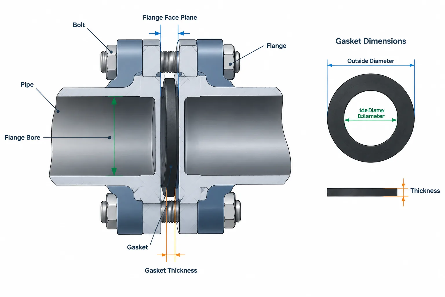
Flange gasket dimensions must be interpreted as part of the complete flange joint rather than as isolated disk measurements. Inside diameter, outside diameter, thickness, bolt-hole geometry, and centering features can each control a different interface in the CAD model.
This guide explains how to represent those features without confusing nominal size with physical bore, supplied thickness with assembled separation, or a gasket’s outer envelope with its active sealing region.
A flange gasket is thin compared with most piping components, but it can affect joint geometry, bore clearance, bolting, material takeoff, and pipe cut length. Treating every gasket as a generic disk may be acceptable in a low-detail arrangement model, but it is not enough for joint detailing or reliable material control.
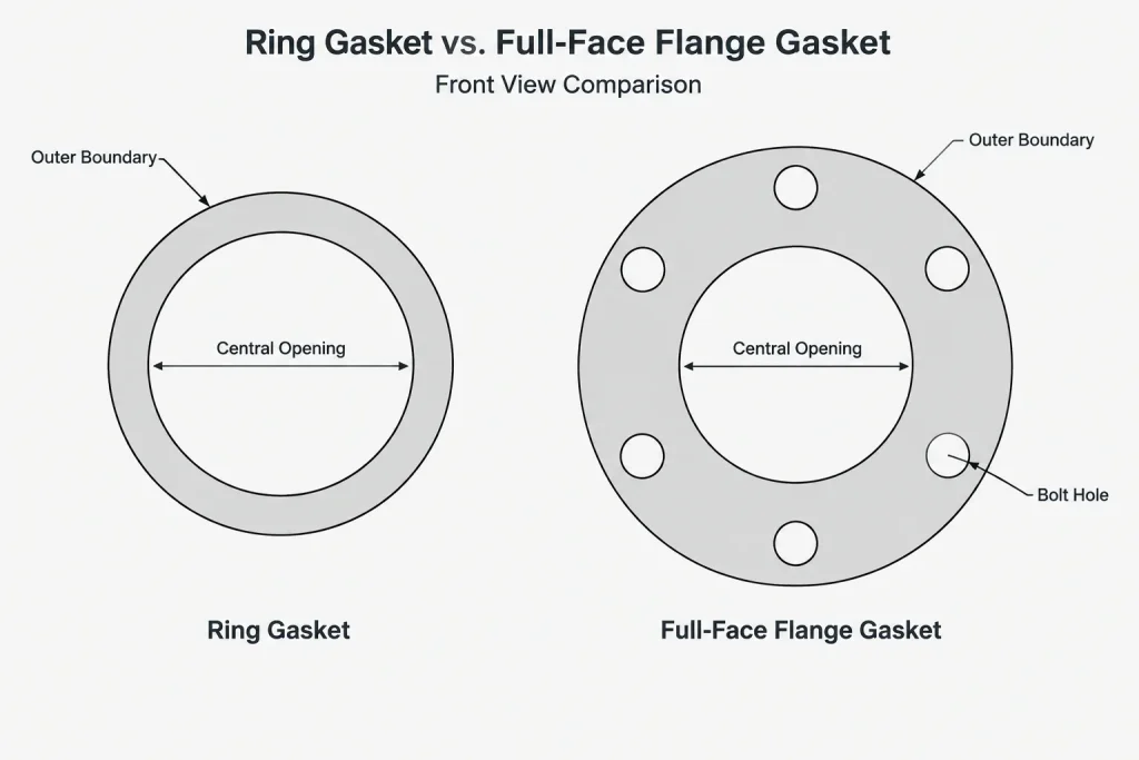
The important dimensions depend on the gasket construction. A simple ring gasket may be described mainly by inside diameter, outside diameter, and thickness. A full-face gasket also has bolt holes. A spiral-wound assembly may include winding, inner-ring, and outer-ring geometry. A ring-type joint uses a metallic ring and matching flange grooves rather than a flat gasket placed across the face.
CAD users therefore need to distinguish between the gasket’s visible envelope, its sealing region, and the dimensions that locate it within the flange joint.
Why gasket geometry matters in a piping model
At a minimum, a piping model must connect the correct flange faces and identify the required gasket. More detailed workflows may also need to show whether the gasket clears the bore, fits inside the bolts, covers the flange face, or requires a particular centering feature.
Gasket geometry can influence:
- the separation represented between mating flange faces;
- pipe and spool cut-length calculations;
- stud or bolt stack-up;
- clearance between the gasket and the flowing bore;
- alignment and centering during assembly;
- material takeoff and joint-kit selection;
- maintenance drawings and exploded joint details;
- compatibility with flange facing and joint type.
A gasket should not be selected from nominal pipe size and flange class alone. The flange facing, gasket construction, material specification, dimensions, service requirements, and project piping class must also agree.
The main gasket dimensions
| Dimension or feature | What it describes | Why it matters in CAD |
|---|---|---|
| Inside diameter | The opening through the gasket or sealing element | Used to check bore intrusion, flow-path clearance, and compatibility with the flange bore |
| Outside diameter | The outer boundary of the gasket or assembly | Controls the modeled envelope and may provide centering within the bolt circle |
| Nominal thickness | The gasket thickness before or as supplied for assembly | May be used for catalog representation, joint stack-up, and material identification |
| Compressed thickness | The resulting thickness after the joint is tightened | Relevant to actual assembled separation, but it is not necessarily a fixed catalog value |
| Bolt holes | Openings in a full-face gasket for the flange bolting | Require the correct hole count, pattern, and orientation if modeled explicitly |
| Centering ring or outer ring | An outer feature that helps position some gasket constructions | Defines an envelope different from the active sealing element |
| Inner ring | An internal support or bore-side feature used in some assemblies | May determine the actual bore-side limit visible in a section view |
Inside diameter is not automatically the pipe ID
The gasket opening should not be assumed to equal nominal pipe size, pipe inside diameter, or flange bore. Pipe ID changes with wall selection, while flange bores and gasket openings are controlled by their own product and joint definitions.
If the gasket ID is too small for the intended flow path, part of the gasket may project into the bore. Intrusion can expose the gasket edge to flow, create a local restriction, or conflict with internal equipment geometry. If the opening is larger, the sealing width and contact location still need to remain appropriate for the selected flange face.
For critical joints, compare the gasket ID with the actual flange bore and connected-component bore rather than checking only the nominal size label.
Outside diameter may be a locating dimension
For a ring gasket used inside the flange bolts, the OD may help center the gasket within the bolt pattern. It is not necessarily the same as the flange OD or raised-face OD. A full-face gasket extends across a larger portion of the flange and includes holes for the bolting.
Some multi-part gaskets have an outer ring that serves primarily as a centering, identification, or handling feature. The outer ring is not the same thing as the active sealing winding. A CAD section or catalog symbol should make that distinction when it affects review or procurement.
Thickness requires a project convention
Gasket thickness is easy to model but easy to misuse. A catalog may store the supplied nominal thickness, while the installed gasket becomes thinner under bolt load. The final amount of compression depends on the gasket design and assembly conditions; it should not be guessed solely to make a model close.
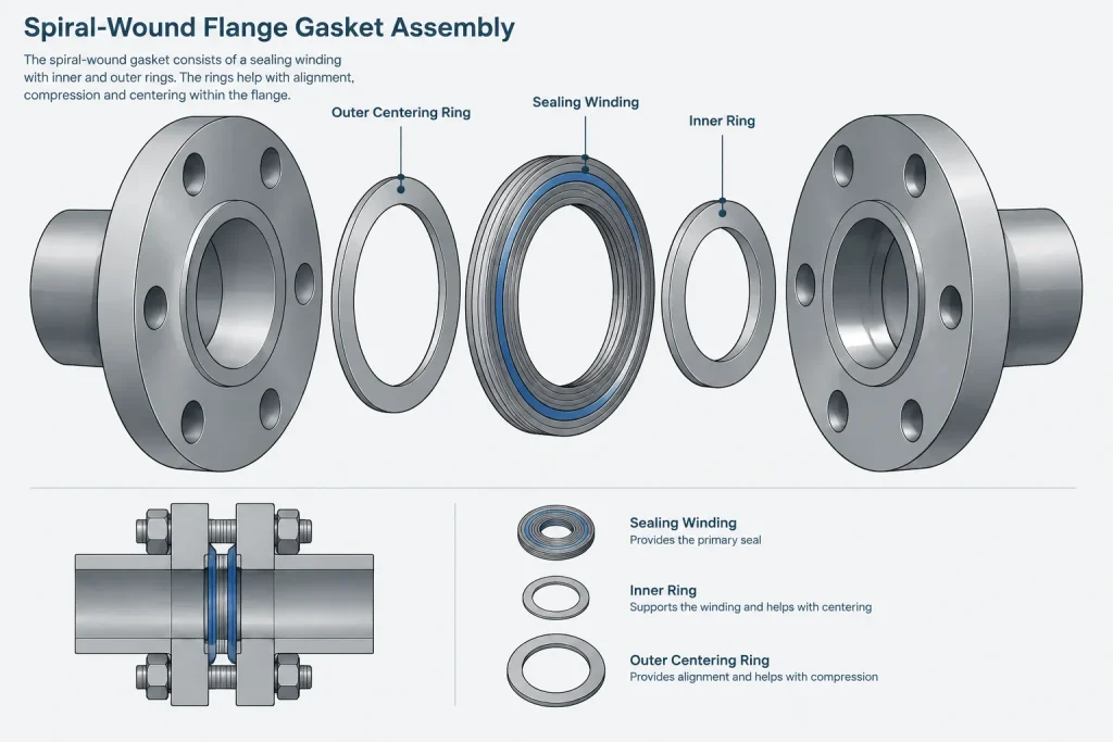
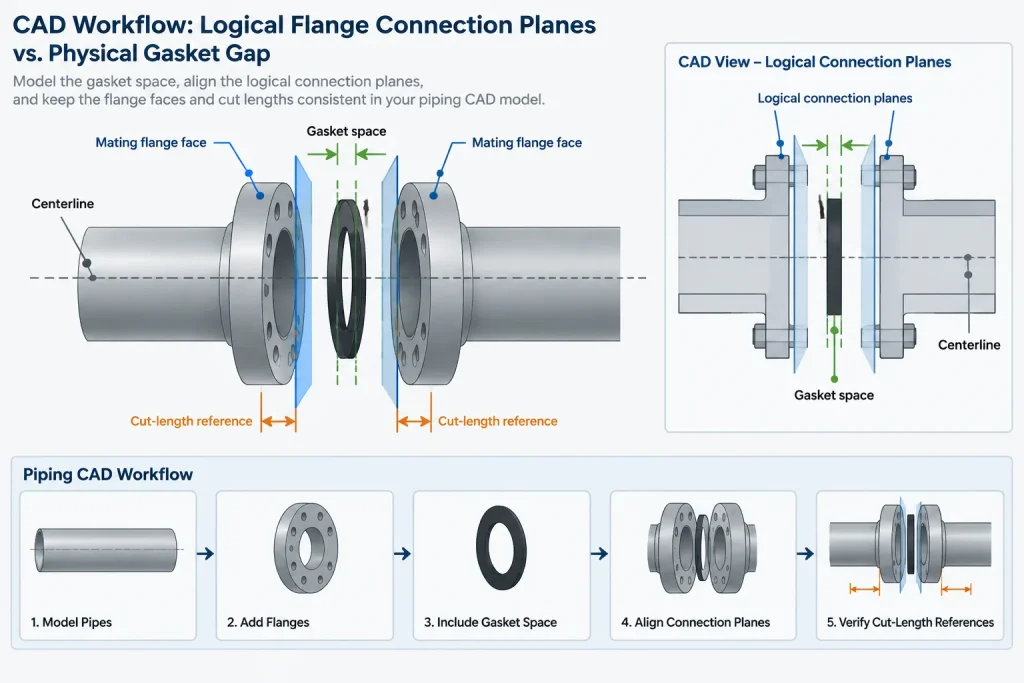
Before adding a gasket thickness to a dimension chain, determine how the project treats flange face planes. Some systems model a physical gasket space between faces. Others connect components at logical face ports and account for gasket allowance through catalog or fabrication rules. If a valve or fitting dimension already follows a defined face-to-face convention, casually adding another allowance can create a dimensional error.
The model, isometric setup, and cut-length calculation should use one documented convention. The same gasket allowance should not be added independently by the component catalog, connection rule, and fabrication worksheet.
Gasket styles need different CAD representations
Ring gasket for flat or raised-face joints
A flat ring gasket is commonly represented as an annular disk between the flange faces. In a general arrangement model, a simplified OD, ID, and thickness may be enough. In a joint detail, the designer may also need to show its relationship to the raised face, bore, and bolts.
Full-face gasket
A full-face gasket extends over the flange face and includes bolt holes. If it is shown in a detailed face view, the bolt pattern cannot be created by scaling a different gasket size. Hole locations must correspond to the selected mating flange definition.
At lower model detail, the bolt holes may be omitted from the solid while their presence remains recorded in component metadata or the material description.
Spiral-wound or multi-part gasket assembly
A spiral-wound assembly may contain a sealing winding plus inner or outer rings. A single simplified disk can represent its space claim, but it should not erase the product distinction in the bill of materials. If the model supports separate attributes, record the gasket construction and ring configuration without creating unnecessary solids for every layer.
Ring-type joint
A ring-type joint is not interchangeable with a flat gasket. It relies on a metallic ring installed in matching flange grooves. The ring section, groove geometry, flange facing, and material selection form a coordinated joint system.
For layout, a simplified ring or joint marker may be sufficient. For a section detail, the ring must be located by the verified groove geometry. Do not approximate a ring-type joint by placing a flat washer-shaped object between generic flange faces.
A practical CAD workflow
- Identify the joint type. Confirm the mating flange facings and whether the joint uses a ring, full-face, wound, jacketed, metallic, or other specified gasket construction.
- Use the piping specification first. The project specification or piping class should establish the permitted gasket family and material requirements. Geometry alone does not establish service suitability.
- Retrieve verified dimensions. Use the applicable standard, approved project data, or manufacturer information. Avoid deriving gasket dimensions by scaling a drawing.
- Define the connection planes. Decide whether gasket thickness creates a modeled physical gap or is handled by connection and fabrication rules.
- Check the bore. Compare gasket ID with both mating bores, especially at reducing joints, lined components, valve seats, and equipment nozzles.
- Check the outer envelope. Verify that the gasket fits the intended face and bolting arrangement. For full-face types, verify bolt-hole compatibility.
- Assign joint metadata. Record the gasket type, size designation, material requirement, specification reference, and any inner- or outer-ring configuration required by the project.
- Review the output. Confirm that isometrics, bills of material, joint reports, and cut lists all interpret the gasket convention consistently.
Common modeling errors
- Using one generic gasket for every facing: This can hide a mismatch between flat-face, raised-face, and ring-type-joint components.
- Matching gasket ID directly to nominal pipe size: Nominal size is a designation, not the physical bore diameter.
- Scaling a gasket block: Scaling changes every feature proportionally even though bore, OD, thickness, and bolt pattern are controlled independently.
- Treating nominal thickness as guaranteed installed thickness: Compression occurs during assembly and should be handled by the applicable joint data and project convention.
- Double-counting the gasket allowance: This happens when both the catalog connection and the spool calculation add the same thickness.
- Modeling only the outer ring: For a multi-part gasket, the visible centering ring does not by itself describe the sealing element.
- Using model geometry as the material specification: Identical-looking solids can represent gaskets with very different constructions and service limitations.
How much detail should the model contain?
The required detail depends on the deliverable. A P&ID usually does not show individual gasket geometry. A plant layout model may need only a thin space claim and a joint record. A fabrication model may need controlled face planes, gasket allowance, and accurate bill-of-material data. A flange-joint detail may require the gasket ID, OD, face relationship, bolting, and section profile.
More geometry is not automatically better. Detailed windings, laminations, or surface textures can make the model heavy without improving coordination. Model the features that control interfaces, clearances, quantities, or assembly, and store the remaining technical requirements as verified data.
Final review principle
A flange gasket is both a sealing component and part of the dimensional joint stack. Its CAD representation should answer three separate questions: what gasket is specified, where it is located, and how its thickness is handled in the project dimensioning convention.
When ID, OD, facing compatibility, and thickness rules are checked independently, the model becomes more useful for layout, fabrication, bolting review, and material control. The final selection still requires confirmation against the governing piping specification, applicable standards, approved component data, and service requirements.
Separate geometry, specification, and assembly data
A dependable gasket record should distinguish between what is drawn, what is specified, and what occurs during assembly. CAD geometry describes the space occupied by the component and its relationship to the flange faces. Specification data identifies the required construction and material. Assembly rules determine how the joint stack is interpreted after tightening.
Keeping these categories separate helps prevent a simplified model from being treated as complete procurement data. It also allows a lightweight gasket solid to remain useful when the bill of materials and joint record contain the verified product requirements.
Coordinate gasket data across deliverables
The gasket definition should be reviewed wherever joint information is transferred between the piping model, isometric output, fabrication documents, material reports, and maintenance details. A consistent identifier is especially useful when the model intentionally omits bolt holes, winding layers, grooves, or other detailed geometry.
- Model review: Confirm the gasket does not intrude into the intended flow path and that its outer envelope agrees with the flange arrangement.
- Dimensional review: Verify which system accounts for the gasket allowance so it is neither omitted nor counted more than once.
- Material review: Confirm that the description identifies the specified gasket construction rather than relying on the appearance of the CAD solid.
- Joint review: Check that both mating components use compatible facing and connection definitions.
Use simplification deliberately
A simplified gasket is appropriate when it preserves the interfaces required by the deliverable. The simplification should be documented through component naming, attributes, or joint metadata so reviewers understand which features are represented physically and which remain data-only.
Where bore clearance, groove engagement, bolt-hole alignment, or sealing-face coverage controls the design, the relevant verified geometry should be shown rather than inferred from a generic symbol.
Frequently asked questions
Is gasket ID the same as pipe ID?
No. Pipe inside diameter depends on the pipe wall definition, while gasket ID is established by the gasket and flange-joint design. The gasket opening should be checked against the actual bores of both mating components.
Should gasket thickness be added to pipe cut length?
Only when the project’s modeling and fabrication convention requires it. Some workflows represent a physical gasket space, while others account for the allowance through connection or fabrication rules. Adding it in more than one place creates an error.
Can one annular CAD block represent every flange gasket?
A generic annular solid may be adequate for an arrangement model, but it cannot communicate every gasket construction. Full-face gaskets, multi-part assemblies, and ring-type joints have different locating and interface features that must remain identifiable in the component data.
Does gasket OD always match the flange OD?
No. The gasket OD may describe a sealing element, a full-face profile, or a centering feature. It should be taken from verified gasket data rather than inferred from the flange’s overall diameter.
Should compressed gasket thickness be modeled?
Use the approved project convention and verified joint data. Compressed thickness depends on the gasket design and assembly conditions, so it should not be estimated merely to close a dimensional chain.
What should be checked at a reducing flange joint?
Compare the gasket opening with both mating bores and review the sealing-face relationship. A nominal size label alone may not reveal bore intrusion or an unsuitable sealing location.