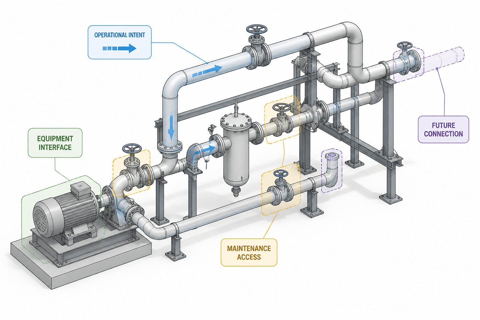
A piping drawing communicates more than the physical path of a line. It also needs to communicate why that path, component orientation, access zone, or connection condition was selected. Without that context, a technically correct CAD model can still be misunderstood during review, fabrication, installation, operation, or later modification.
This guide explains how to capture piping design intent in CAD without turning the model into an overcrowded collection of comments. It separates functional reasoning from geometry and shows how to place each type of information in a controlled, reviewable project record.
A piping model can be geometrically correct and still be difficult to understand. Lines may connect, fittings may appear in the right locations, and dimensions may check out, yet the drawing can leave important questions unanswered: Why is this valve oriented that way? Which side is intended for removal? Is a short branch temporary, operational, or part of a future connection? What must remain adjustable during construction?
These questions relate to design intent. Design intent is the functional reasoning behind the arrangement shown in a CAD model or drawing. It explains what the geometry is meant to accomplish, not just what the geometry looks like. Capturing that reasoning helps designers, reviewers, fabricators, operators, and future project teams interpret the piping consistently.
This guide presents a practical workflow for recording design intent without overcrowding the model or replacing project-specific engineering documents.
What design intent means in piping CAD
In piping work, design intent connects physical arrangement to function. It may describe the purpose of a routing choice, the required operating position of a component, the relationship between a line and nearby equipment, or a condition that must be preserved during fabrication and installation.
Design intent is not a substitute for calculations, process documentation, material specifications, stress analysis, or approved project criteria. Instead, it provides context that may not be obvious from dimensions and symbols alone.
- Functional intent: what the line or component is intended to do during operation.
- Access intent: which components require approach, observation, adjustment, or removal space.
- Construction intent: how the arrangement is expected to be fabricated, lifted, installed, or connected.
- Maintenance intent: what must be removable or reachable without unnecessary dismantling.
- Coordination intent: which interfaces, clearances, and reference elevations must remain stable.
- Future-work intent: whether a capped branch, blind connection, or reserved space has a planned purpose.
Why geometry alone is not enough
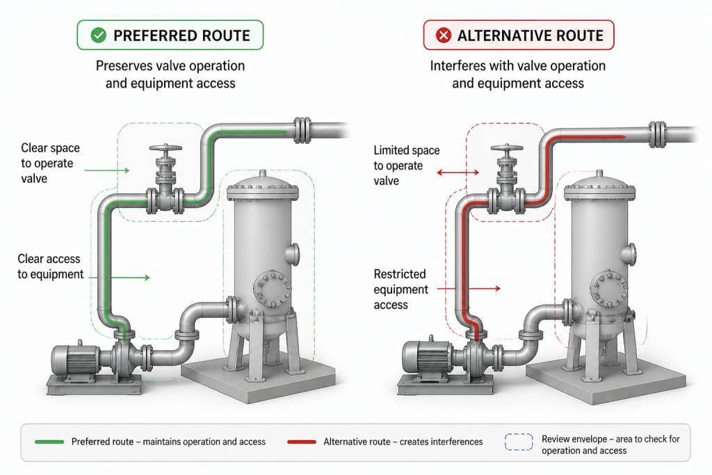
CAD geometry shows location and shape, but it often does not show priority. Two routing options may both connect the same equipment, while only one preserves access to a valve, allows a spool to be removed, or keeps a drain point usable. If the reasoning is not recorded, a later revision may unintentionally remove a critical feature.
Design intent is especially valuable when:
- multiple disciplines share the same model or drawing set;
- the designer who created the route will not perform the next review;
- field changes are likely during construction;
- equipment nozzles, structural steel, or access platforms may move;
- the line has operational, maintenance, or safety-related constraints;
- the model will be reused for brownfield modifications or future expansion.
A useful rule is to document any decision that a competent reviewer could not reliably infer from the model, line list, P&ID, or material data alone.
Where to record design intent
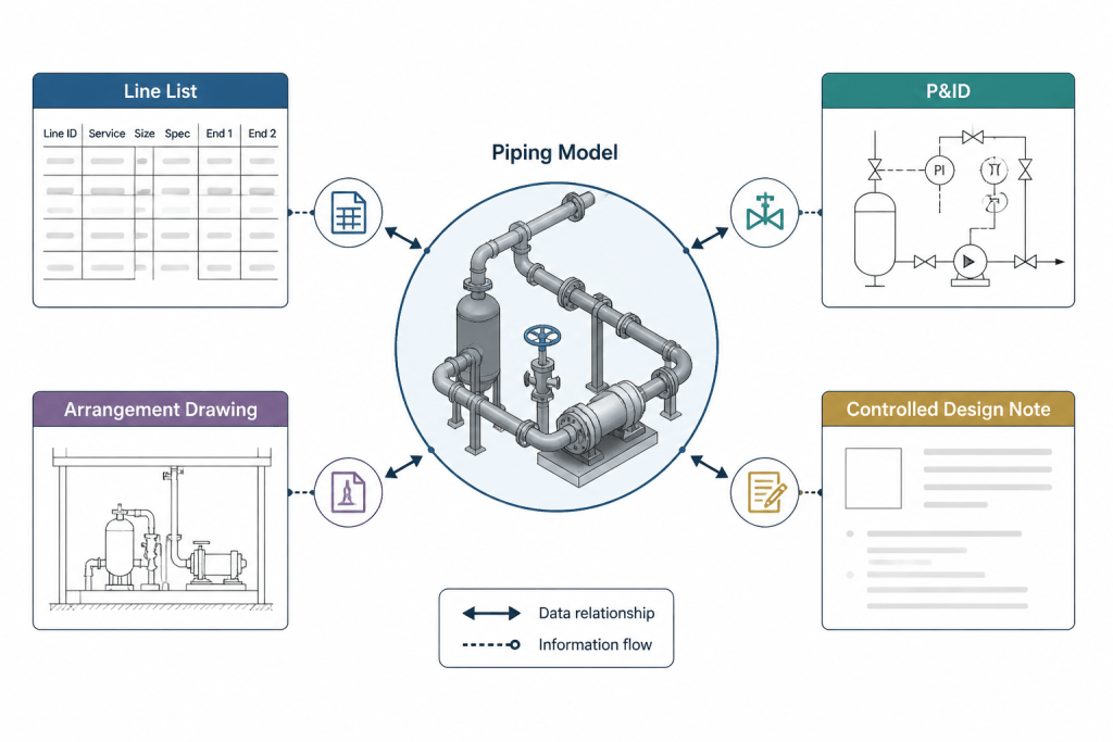
Design intent should be stored where the intended audience can find it and where it will remain associated with the affected item. A single note location is rarely sufficient for every type of information.
| Information type | Useful location | Purpose |
|---|---|---|
| Line function or operating relationship | Line list, P&ID, or controlled line note | Preserves process-level meaning |
| Local routing rationale | CAD note, model property, or design review record | Explains a geometric decision |
| Component access requirement | Model annotation, arrangement drawing, or access study | Supports layout and review |
| Fabrication or installation constraint | Isometric note, spool information, or construction document | Communicates execution requirements |
| Temporary or future condition | Controlled note with status and ownership | Prevents temporary geometry from being mistaken for final design |
Do not hide important intent only in an informal comment, personal layer, or untracked email. If the information can affect routing, procurement, fabrication, operation, or maintenance, it should be placed in a controlled project record.
Classify the intent before adding a note
Before writing a note, identify what kind of decision it explains. Classification makes notes easier to review and reduces vague comments such as “keep clear” or “install as required.”
Operational intent
Use this category when the arrangement supports normal operation, isolation, draining, venting, sampling, flow control, or equipment service. State the function rather than merely describing the component. For example, a note might explain that a valve is positioned for operation from a designated access side, subject to the project’s approved arrangement.
Maintenance intent
Describe what must be removed, inspected, adjusted, or reached. Identify the affected item and the direction or area in which access is expected. Avoid relying on an unexplained empty region in the model; a clear note makes the purpose of that space reviewable.
Construction intent
Construction notes can explain a planned field connection, a preferred spool division, an installation sequence concern, or a component that must remain loose until alignment is confirmed. Such notes should be coordinated with fabrication and field execution documents before issue.
Interface intent
Use this category for relationships with equipment, structures, platforms, existing piping, electrical systems, or other disciplines. A good interface note identifies the dependency: for example, a route may be held to a specific nozzle orientation, structural opening, or access platform edge.
Status intent
Temporary, proposed, existing, relocated, and future items should be distinguishable. Status is part of design intent because it affects how reviewers interpret the geometry and whether it belongs in material takeoffs, construction scope, or operating documentation.
Write notes that explain decisions
An effective design-intent note is specific, observable, and limited to one decision. A useful structure is:
- Subject: identify the line, valve, branch, support interface, or area.
- Intent: state what the arrangement is meant to achieve.
- Constraint: identify the condition that must not be lost.
- Verification: state how the reviewer can confirm it.
For example, instead of writing “maintain access,” describe the component or operation involved, the side from which access is expected, and the drawing or model view where the condition can be checked. The note should not invent a clearance value or imply a code requirement unless that value has been established by the project’s governing documents.
Use neutral language for unresolved items. “Confirm access direction with operations” is more useful than silently choosing an orientation and allowing the model to suggest that the decision is final.
Show intent graphically when possible
Text is important, but a graphic cue can make the requirement easier to review. Depending on the CAD environment and project conventions, useful methods include:
- an equipment or maintenance access envelope represented on a review layer;
- a clearly labeled reference plane or control elevation;
- a continuation or future-connection symbol tied to a controlled note;
- a highlighted interface point for an existing-to-new connection;
- a directional annotation showing the intended removal or operating approach;
- a status convention separating existing, new, temporary, and future geometry.
Graphic aids should be distinguishable from physical piping. Use approved layer, color, linetype, and annotation conventions so that a review envelope is not mistaken for a pipe, support, or permanent structure.
Connect design intent to model data
Where the CAD or plant-design system supports custom properties, associate intent with the relevant object rather than storing everything in a general drawing note. Possible fields include intent category, status, responsible discipline, review state, affected document, and a short explanation.
Keep structured fields concise. A property such as “maintenance access required” is useful when it can be filtered, reviewed, or reported. Detailed reasoning can remain in a linked design record or controlled note. The goal is traceability, not a large paragraph attached to every component.
Be careful with copied objects. When a valve, branch, or line segment is duplicated, verify that its intent data still applies. Reused CAD blocks and template properties can carry obsolete notes into new areas if they are not checked during placement.
Review design intent at project milestones
Intent should be checked whenever the geometry or project status changes. A practical review sequence includes:
- Confirm that the initial intent agrees with process and equipment information.
- Review whether routing changes preserve the original function and access.
- Check that interfaces remain coordinated after structural or equipment revisions.
- Verify that temporary and future items have the correct status.
- Remove or close obsolete notes before issuing the drawing.
- Confirm that field changes are reflected in the controlled model or record.
During a review, ask a simple question: if another engineer had to modify this area later, would the reason for the current arrangement be clear? If not, the model may need a better note, a graphic cue, or a reference to the controlling document.
Common mistakes to avoid
- Documenting appearance instead of purpose: “Valve shown horizontal” does not explain why the orientation matters.
- Using vague restrictions: “Do not move” should identify the dependency and the consequence of movement.
- Mixing approved and unresolved intent: Mark open decisions clearly so they are not treated as final.
- Overloading the model: Not every design thought belongs as a permanent CAD annotation.
- Failing to update notes: An obsolete explanation can be more misleading than no explanation.
- Confusing intent with compliance: A note explains a project decision; it does not replace engineering verification or governing requirements.
A practical final check
Before issuing a piping drawing or model, review the areas where geometry is most likely to be reinterpreted: equipment connections, access zones, removable components, branch arrangements, temporary connections, existing interfaces, support relationships, and future tie-in points. Confirm that important decisions are visible, traceable, and assigned the correct status.
Good piping CAD communicates more than connectivity. It preserves the reasoning that makes the arrangement useful, buildable, operable, and maintainable. By recording design intent at the right level and in the right project record, teams can make future revisions with less guesswork and fewer accidental changes to the original design.
How to use design-intent information during review
Design-intent notes are most valuable when they help a reviewer make a decision. A useful note should make the affected object easy to identify, explain the reason for the arrangement, and point to the condition that must be preserved. If the note cannot be checked in the model, drawing set, or controlling project document, it may be too vague to support a reliable review.
Reviewers should also distinguish between a design requirement, an open coordination item, and a record of an existing condition. These categories can look similar in a CAD view but have different consequences for approval and revision. Clear status labeling prevents a proposed route from being mistaken for an approved arrangement and prevents a temporary feature from being carried into final documentation without review.
Relationship to piping drawings and project records
Design intent works best as part of a coordinated information system. The CAD model can show local relationships and graphical cues, while the line list, P&ID, equipment information, isometric, design review record, and construction documents provide the broader context. The same decision should not be copied into multiple uncontrolled locations unless each record has a clear purpose and update responsibility.
When a routing decision affects several disciplines, record the dependency where those disciplines will encounter it. For example, an equipment interface may require coordination with mechanical layout, structural design, access planning, and field installation. A short model property may identify the issue, while a controlled review record preserves the reasoning and resolution.
Practical editing principle
Use the smallest amount of information that preserves the decision. A concise, searchable property can identify the intent category or status, while a focused annotation can explain the local condition. More detailed justification belongs in the appropriate controlled project record. This approach keeps the CAD model readable while preserving the information needed for future engineering work.
Frequently asked questions
What is design intent in piping CAD?
Design intent is the functional reasoning behind a piping arrangement. It explains what the geometry is intended to achieve, such as preserving access, supporting operation, coordinating an interface, or allowing a planned future condition.
Why is design intent important when the model is geometrically correct?
Geometry shows location and shape, but it may not show priority or purpose. Recording intent helps later reviewers understand which arrangement features must be preserved and which conditions may still be open to change.
Where should piping design intent be documented?
The appropriate location depends on the information. Local routing rationale may belong in a CAD note or model property, while process meaning, construction requirements, and controlled decisions may belong in the line list, P&ID, isometric, design review record, or construction documentation.
Should every design decision be added as a CAD annotation?
No. Excessive annotations can make a model difficult to read. Use concise graphical cues or properties for information that must remain associated with an object, and place detailed reasoning in the controlled record intended for that decision.
How should unresolved design intent be shown?
Open decisions should be identified as unresolved and assigned to the appropriate reviewer or discipline. Neutral wording is preferable to silently presenting an unconfirmed arrangement as final design.
Does a design-intent note replace engineering verification?
No. A note explains a project decision or dependency, but it does not replace calculations, approved criteria, material requirements, stress evaluation, process documentation, or other required engineering verification.