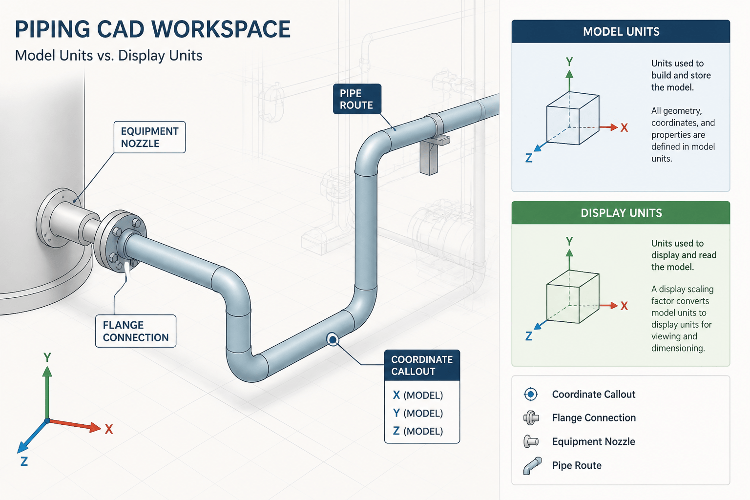
Unit control is one of the most practical forms of quality assurance in piping CAD. A drawing may appear clean and coordinated while still containing a scale, annotation, or data interpretation error that affects downstream design and fabrication work.
The safest approach is to treat units as a coordinated system rather than as a single CAD setting. Model geometry, displayed dimensions, coordinates, elevations, component identifiers, and imported references all need a clear relationship. The guidance below explains how to establish that relationship and how to review it before information is issued.
Unit errors in piping CAD rarely come from difficult mathematics. They usually come from inconsistent assumptions: a model created in millimeters, a title block labeled in inches, a component library using nominal pipe size, or a copied detail whose dimensions were never converted. Because piping drawings combine geometry, equipment data, schedules, specifications, and fabrication information, a small unit mistake can spread across many deliverables.
A reliable unit workflow begins by separating three ideas: the units used to create geometry, the units used to display dimensions, and the terminology used to identify piping components. These are related, but they are not interchangeable. This guide explains how to control them during CAD setup, modeling, annotation, review, and data exchange.
Why units matter in piping drawings
CAD software stores geometry according to a drawing or model unit system. A line may represent a physical length in millimeters, inches, or another project-approved unit, but the software does not always know what that line represents. It may simply store a numerical distance. The meaning is established by the template, project settings, component library, and drawing conventions.
In piping work, units affect more than linear dimensions. They can influence:
- Pipe and fitting geometry imported from catalogs or external models
- Equipment nozzle locations and connection elevations
- Flange, valve, and fitting face-to-face dimensions
- Support locations and structural interfaces
- Coordinate data exchanged with plant or building models
- Bill of material descriptions and procurement notes
- Isometric dimensions, spool dimensions, and fabrication annotations
A drawing can look visually plausible while still being wrong if the geometry was scaled during import or the annotations report a different unit system from the model.
Separate model units from display units
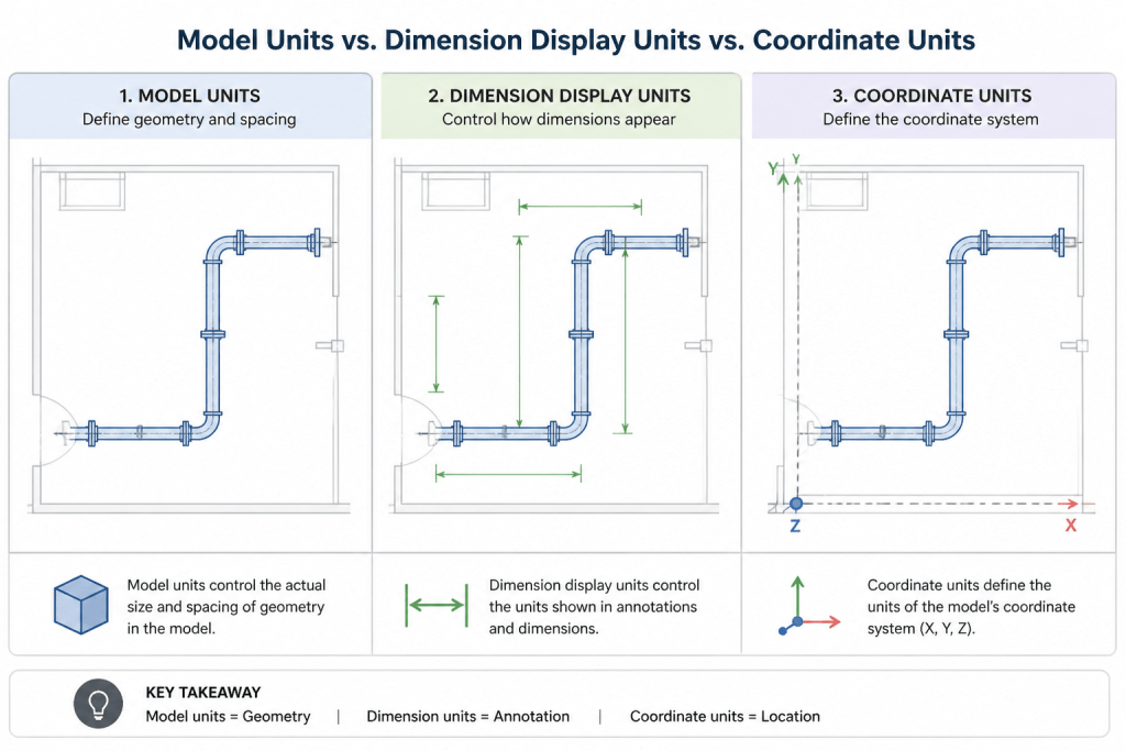
The first check is to distinguish the units used by the CAD model from the units shown to the reader. A project may model and dimension in the same unit system, but that should be an intentional decision rather than an assumption.
| Unit control | What it governs | Typical review question |
|---|---|---|
| Model or insertion units | How geometry is created, inserted, and exchanged | Will an external block or reference file arrive at the correct physical size? |
| Dimension style units | How measured values are displayed | Do annotations report the same unit convention expected by the project? |
| Coordinate and elevation units | How locations are documented | Are plant coordinates and drawing elevations using a consistent basis? |
| Schedule and specification notation | How size, thickness, rating, and material information are described | Are textual properties being mistaken for geometric dimensions? |
Changing the dimension display alone does not necessarily resize the model. Conversely, scaling geometry does not automatically correct existing text, blocks, attribute values, or database properties. Check both the physical model and the reporting settings.
Nominal pipe size is not a measured dimension
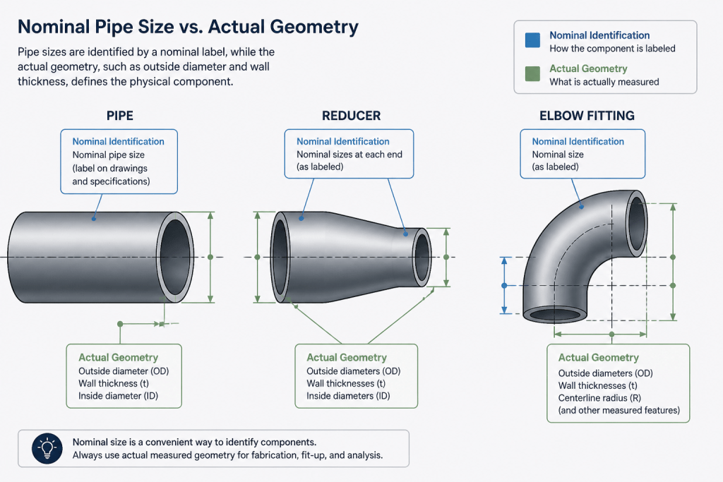
One of the most important terminology checks is the difference between nominal size and an actual measured dimension. Nominal pipe size is a designation used to identify a pipe or connection within a recognized sizing system. It should not automatically be treated as the outside diameter, inside diameter, wall thickness, or a dimension that can be measured directly from a drawing.
The actual geometry depends on the selected pipe product, wall designation, material, connection type, and component standard or project specification. A fitting connected to a nominal pipe size can have a face-to-face, center-to-end, or takeout dimension that is completely different from the size label used to identify it.
For CAD work, use the nominal size as a component identity or specification attribute, while using the authoritative dimensional data for geometry. Do not replace a catalog value with a conversion calculated from the nominal designation.
Plan a unit convention before modeling
A project template should establish the unit convention before the first routed line is created. At minimum, define the following items:

- Modeling units for piping and equipment geometry
- Dimension units for plans, sections, and isometrics
- Elevation and coordinate conventions
- Decimal or fractional display rules
- Rounding and precision expectations
- Unit suffixes or general notes required on drawings
- Rules for imported blocks, external references, and vendor models
Also identify where the project uses a different convention. A fabrication detail, vendor drawing, or existing-condition survey may use another unit system. Such information can be incorporated, but its original units should remain visible during checking until the conversion and interpretation are verified.
Control imported geometry and external references
Imported content is a common source of unit errors. Blocks, equipment layouts, valve symbols, and reference drawings may contain no reliable unit metadata. Some files rely on insertion settings; others were prepared using a title block convention that is not embedded in the geometry.
Before accepting imported content, compare a known physical dimension against the source document or approved component data. If the size is wrong, correct the insertion or conversion method rather than stretching individual objects manually. Manual stretching can distort symbols, break attribute positions, and create uncertainty about which dimensions remain trustworthy.
For external references, confirm the units at both ends of the exchange. A file can have correct geometry internally but still insert incorrectly into a host model if the host drawing interprets the source units differently. Record the conversion decision in the project workflow or drawing notes so that later users do not repeat the operation.
Use dimension styles that communicate clearly
Dimension styles should make the unit convention obvious without overwhelming the drawing. Check the following settings:
- Displayed unit format and unit suffix
- Decimal, fractional, or engineering notation
- Rounding and decimal precision
- Alternate-unit display, if used
- Zero suppression rules
- Scale behavior for model-space and paper-space annotations
- Text placement and readability at the plotted scale
Avoid showing alternate units merely because the CAD software makes the option available. Dual-unit dimensions can help with coordination, but they can also crowd a drawing and create two values that appear to conflict when rounding is not controlled. Use them only when the project requires them and define which value is primary.
Review the unit-sensitive parts of a piping drawing
A unit review should examine more than a few random dimensions. Focus on locations where a conversion error could affect connectivity or interpretation:
- Equipment nozzle coordinates and centerline elevations
- Pipe rack and structural reference points
- Flange faces and valve end locations
- Branch connection positions
- Support attachment points
- Insulation or clearance envelopes
- Spool break locations and field connection points
- Dimensions copied from vendor or existing-condition drawings
Compare the model measurement, the displayed annotation, and the associated data record. If these three sources do not agree, determine whether the problem is a geometry error, a display-setting error, a rounding issue, or a property-labeling error.
Common unit mistakes and better controls
| Common mistake | Why it happens | Better control |
|---|---|---|
| Imported geometry appears at the wrong size | Source and host insertion units differ | Verify a known dimension before placing the file |
| Nominal size is used as outside diameter | Size labels are mistaken for physical dimensions | Use approved dimensional data for geometry |
| Model and title block use different conventions | Template settings were copied without review | Check model units, dimension styles, and notes together |
| Rounded dimensions create apparent gaps | Displayed values hide small differences | Review model measurements at suitable precision |
| Converted vendor data loses traceability | Only the final values are retained | Preserve the source unit basis during checking |
A practical pre-issue checklist
Before issuing a piping drawing or model, confirm that:
- The project unit convention is stated in the template, notes, or drafting procedure.
- Model units and display units have been checked independently.
- Imported blocks and references were tested against known dimensions.
- Nominal sizes are not being used as substitutes for actual component dimensions.
- Coordinates, elevations, and dimensions use the intended unit basis.
- Dimension styles, precision, rounding, and suffixes are consistent.
- Vendor, existing-condition, and converted information remains traceable.
- Critical interfaces were checked in the model rather than from rounded text alone.
Final perspective
Good unit control is a coordination practice, not just a CAD preference. The goal is to ensure that geometry, annotations, component data, and project documents describe the same physical arrangement. Treat nominal size as identification, use authoritative dimensional information for modeling, verify imported content before routing, and review the unit basis at every interface. These habits reduce avoidable rework and make piping drawings easier to fabricate, review, and maintain.
How to think about unit control across the drawing workflow
A useful unit review follows the information as it moves through the project. First, confirm how the model represents physical geometry. Next, check how that geometry is measured and displayed. Finally, verify that component data and exchanged files use terminology that does not contradict the model.
This approach helps separate several problems that can look similar on paper. A wrongly scaled reference file is a geometry problem. A correct model with misleading dimension formatting is a display problem. A correct physical component described with an incorrect size interpretation is a data problem. Each requires a different correction, so identifying the failure type is more effective than simply rescaling the drawing.
Use interfaces as review priorities
Not every location in a piping model has the same consequence when units are misunderstood. Interfaces deserve early attention because they connect piping information to other disciplines or to physical fabrication. Equipment connections, structural supports, vendor models, flange locations, and field connection points are especially useful review locations.
At each interface, compare the geometry, the annotation, and the associated property or schedule information. This three-way check can reveal whether the issue is caused by conversion, rounding, labeling, or an incorrect source value. It also creates a clearer audit trail when information comes from an external drawing or model.
Keep conversion decisions visible
Conversions should be documented as part of the drawing or model workflow, not treated as an informal adjustment made by one user. Preserve the source unit basis during checking, identify the receiving model convention, and record how the content was inserted or interpreted. This is particularly important for vendor information and existing-condition documentation, where later users may not have access to the original authoring environment.
A consistent template, controlled component library, clear dimension style, and disciplined review process work together. None of these controls replaces engineering judgment, but they make errors easier to detect before they affect coordination, procurement, fabrication, or field work.
Frequently Asked Questions
Are CAD model units and dimension display units the same thing?
No. Model units control how geometry is created, inserted, and exchanged, while dimension settings control how measured values are presented to the reader. They may use the same convention, but they must be checked independently.
Can changing the dimension style resize piping geometry?
Normally, changing the dimension display changes the reported value or format, not the physical model. Geometry must be checked separately, especially after importing or converting external content.
Why should nominal pipe size not be used as a measured CAD dimension?
Nominal pipe size identifies a component within a sizing system. It does not automatically define the outside diameter, inside diameter, wall thickness, or fitting geometry. Authoritative dimensional data should control the modeled component.
What should be checked before importing a piping reference file?
Verify the source unit basis, compare a known physical dimension with the source information, and confirm how the host drawing interprets insertion units. Record the conversion or insertion decision after it has been verified.
When are alternate-unit dimensions useful?
Alternate units can support coordination when different project participants use different conventions. They should be used only when required, with a clearly identified primary value and controlled rounding so the annotations do not appear contradictory.
Which parts of a piping drawing are most sensitive to unit errors?
Prioritize equipment connections, elevations, coordinates, flange and valve locations, branch connections, supports, clearance envelopes, spool breaks, and information copied from vendor or existing-condition drawings.