Flanges are small components with a large effect on piping coordination. In a CAD model, the flange must communicate more than its outline: it should show how the pipe connects, where the mating face is located, and how the component will be identified in project documentation.
This guide provides a practical way to compare common piping flange types in CAD. Use it when reviewing model geometry, selecting library components, preparing fabrication information, or checking whether the bill of materials agrees with the modeled connection. Actual selection remains subject to the project specification, piping material specification, approved component library, and engineering review.
Flanges can look deceptively similar in a piping model. Most are represented as circular plates or compact connection symbols, yet their interfaces with pipe, gaskets, bolts, and adjacent components can differ substantially. Choosing the correct flange type in CAD is therefore more than selecting a familiar block. The model must communicate how the joint is made, where the pipe terminates, which dimensions control the connection, and what information belongs in the bill of materials.
This guide compares common piping flange types and explains how to represent them consistently in CAD. It is intended to support drafting and coordination. The governing project specification, piping material specification, approved component library, and engineering review remain the controlling sources for actual selection.
Why flange type matters in a CAD model
A flange affects both geometry and documentation. Its face location can control a valve or equipment connection, while its attachment method affects weld details, field work, inspection planning, and spool boundaries. A visually plausible flange can still be wrong if it has the wrong end connection, face-to-face relationship, or component identity.
When reviewing a flange in CAD, check four related questions:
- How does the flange attach to the pipe? It may be welded, threaded, or used with a separate stub end and lap-joint ring.
- Where is the pressure-retaining face? The gasket contact surface must align with the mating component or equipment nozzle.
- How is the joint identified? The component description should distinguish the flange type from its nominal size, pressure designation, material, facing, and other project data.
- What does the model need to show? A fabrication model may require more detail than a general arrangement drawing, but neither should imply a connection that the specification does not support.
Common piping flange types compared
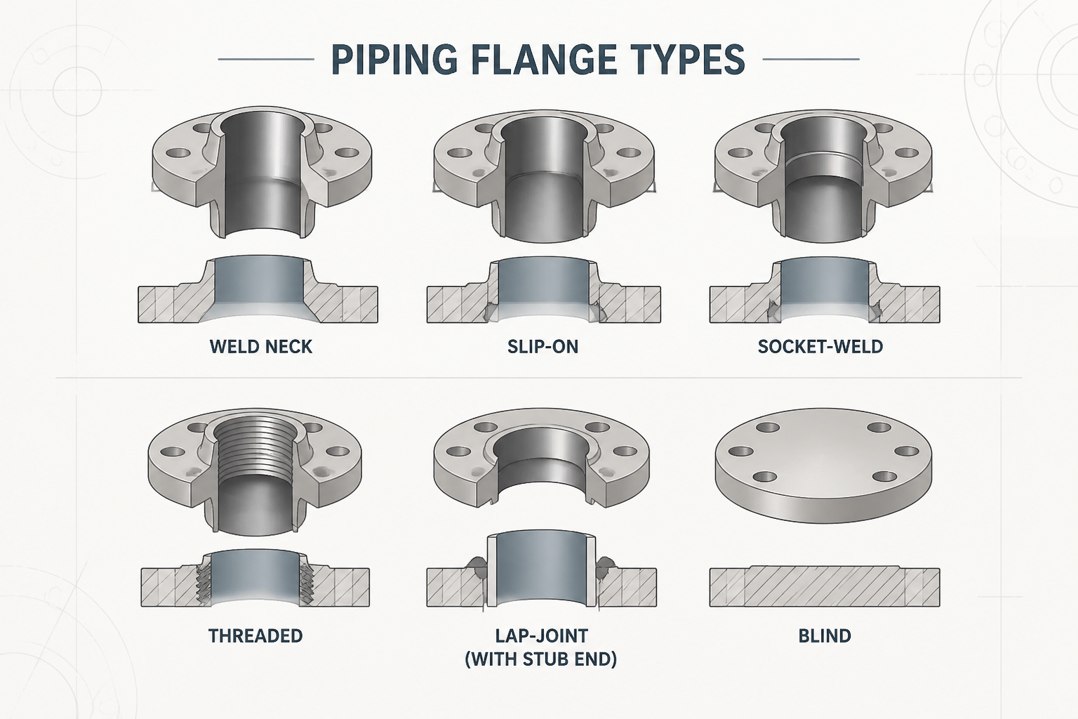
| Flange type | Primary attachment concept | CAD detailing emphasis |
|---|---|---|
| Weld neck | Butt-welded to the pipe | Show the tapered hub and the relationship between the pipe end, weld location, and flange face. |
| Slip-on | Placed over the pipe and welded | Represent the flange as surrounding the pipe; do not model it as a butt-weld end unless the library component specifically defines that geometry. |
| Socket-weld | Pipe enters a socket and is welded around the outside | Show the socket connection and preserve the correct face location for the mating component. |
| Threaded | Attached through internal threading rather than a pipe weld | Identify the threaded end clearly and avoid displaying a weld symbol or weld gap that does not apply. |
| Lap-joint | Used with a separate stub end and a loose backing flange | Model the stub end and backing flange as related but distinct components. |
| Blind | Closes a flanged opening | Show a solid closure at the flange face and confirm whether a vent, drain, test connection, or other feature is required by the design. |
Weld neck flanges
A weld neck flange has a hub that transitions toward the pipe and is normally associated with a butt-welded pipe connection. In a CAD model, the hub is an important identification feature. Replacing it with a flat ring can make the component resemble a slip-on flange and can obscure the intended weld location.
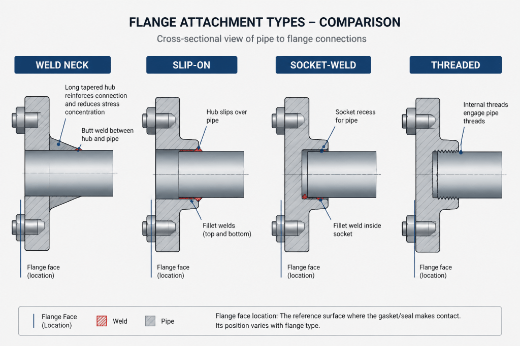
For a weld neck connection, align the pipe centerline with the flange axis and place the flange face at the required connection plane. In an isometric or fabrication view, the weld location should remain distinguishable from the gasket face. The component tag and bill of materials should also identify the flange as a weld neck type rather than relying on geometry alone.
Slip-on flanges
A slip-on flange fits over the pipe and is attached with welds at the pipe interface. Its external appearance may be relatively simple, which makes it easy to confuse with other flange styles in a low-detail model.
Use the approved library representation and confirm how the project defines the pipe end relative to the flange. This matters when generating spool dimensions, weld maps, and material takeoffs. A model that shows only the outer flange diameter may not provide enough information to establish the fabrication arrangement.
Socket-weld and threaded flanges
Socket-weld flanges and threaded flanges are often used where a compact connection or a particular installation method is required. Their CAD representations should make the end connection legible, especially in small-bore piping where several components may be crowded together.
For a socket-weld flange, check the pipe insertion relationship and the location of the flange face. For a threaded flange, show or label the threaded connection according to the project drafting practice. Do not add a weld representation simply because the flange is adjacent to a pipe. The connection method belongs to the component definition and should agree with the material specification and item description.
Lap-joint flange assemblies
A lap-joint arrangement is an assembly rather than a single interchangeable flange item. It includes a stub end that provides the pipe-facing contact and a loose backing flange that supplies the bolting interface. The backing flange can rotate to assist bolt-hole alignment, but that does not make it equivalent to a permanently attached flange type.
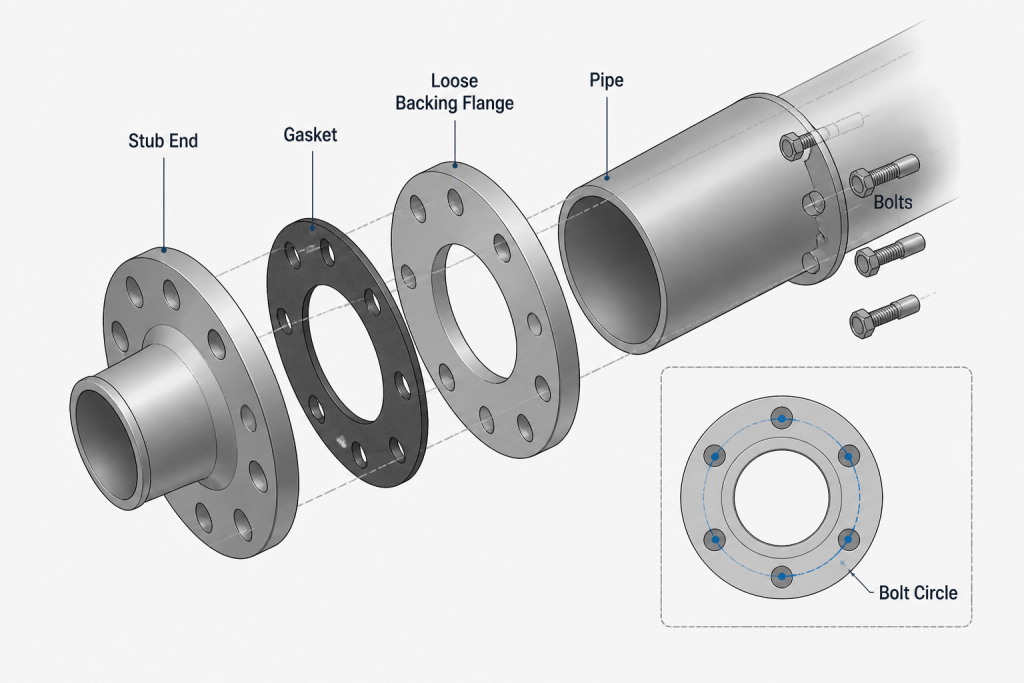
In CAD, keep the stub end and backing flange identifiable as separate parts. This improves material takeoff accuracy and prevents the assembly from being counted as one generic flange. It also helps reviewers distinguish the pipe-facing surface from the bolting component.
Blind flanges
A blind flange closes the end of a flanged connection. Unlike a flange intended to connect two open passages, it must be represented as a solid closure. In layouts, a blind flange may appear at equipment isolation points, temporary termination points, or future connection locations, but the reason for its use should come from the design documents.
Review blind flange locations carefully when they occur near vents, drains, test boundaries, or removable equipment. A closure that appears correct in plan view may conflict with access requirements or with a required temporary connection. The CAD model should show the flange face and bolting relationship without inventing additional openings or attachments.
CAD checks that apply to every flange type
Check the connection axis
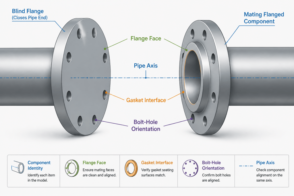
The flange bore, pipe centerline, gasket face, and mating component should share the intended axis. Small angular or positional errors can create visible misalignment in an isometric and can become significant at equipment nozzles or valve connections.
Check the face-to-face relationship
Use the approved component dimensions when locating the flange face. Do not estimate the position from a block that is intended only for schematic display. Face location affects valve placement, spool length, equipment clearance, and field fit-up.
Check the flange identity
Confirm that the tag, description, specification assignment, and material takeoff all identify the same flange type. A correct-looking model with an incorrect component code can still produce the wrong procurement or fabrication information.
Check mating conditions
At each flanged joint, verify the mating flange, gasket representation or note, bolt-hole orientation, and available assembly space. These checks complement—not replace—the project requirements for facing, bolting, gasket selection, and pressure designation.
How to improve a flange library
A reliable flange library should separate geometry from project data. Store the component type, nominal size, pressure designation, material, facing description, end connection, and reference identifiers as controlled properties rather than embedding them only in a block name.
- Use consistent insertion points, preferably tied to the flange axis and face plane.
- Provide clear connection ports for pipe, valve, fitting, or equipment interfaces.
- Keep weld neck, slip-on, socket-weld, threaded, lap-joint, and blind components distinct.
- Include a display level appropriate to plans, isometrics, and fabrication views.
- Test the component in a short sample connection before releasing it for project use.
Final review checklist
Before issuing a piping drawing or model, confirm the following:
- The flange type matches the piping specification and component record.
- The attachment method is represented correctly and is not confused with an adjacent weld.
- The flange face is located at the intended connection plane.
- Lap-joint assemblies show the stub end and loose flange as distinct items.
- Blind flanges are shown as closures rather than open-ended connections.
- Bolting, gasket, facing, and access information is coordinated with the applicable project requirements.
- The CAD geometry, tag, bill of materials, and fabrication documentation agree.
Flange selection is an engineering and specification decision, while flange detailing is a communication task. A good CAD model preserves both: it shows how the joint is physically arranged and carries enough controlled data for reviewers, fabricators, and downstream documentation to identify the correct component.
How to read flange geometry in a piping model
A flange model should be reviewed as part of a connection system rather than as an isolated circular object. Start at the pipe end and follow the connection toward the gasket face, mating component, and bolting interface. This approach helps reveal errors that may not be obvious in a plan view or simplified block.
Separate visual resemblance from component identity
Several flange types can appear similar when displayed at a low level of detail. The reliable distinction is the attachment concept and the associated component data. A hub, socket, threaded end, stub end, or solid closure can change how the item is fabricated, installed, counted, and reviewed.
Use the model for coordination, not specification substitution
CAD geometry can communicate the intended arrangement, but it should not be used to infer unapproved material, facing, bolting, gasket, or pressure information. Controlled properties and project records should carry those details. Where the model is simplified, the tag and component description should still preserve the correct flange identity.
A practical review sequence
- Identify the flange type from the component record and visible connection geometry.
- Confirm the pipe axis, flange face, and mating component share the intended alignment.
- Check whether the depicted weld, thread, socket, stub end, or closure matches the selected type.
- Review assembly clearance, bolt-hole orientation, and access around the joint.
- Compare the model, tag, material takeoff, and fabrication documentation before issue.
This sequence is useful for both new modeling and model review because it checks physical arrangement and information quality together.
Frequently asked questions
Why is flange type important in CAD?
Flange type affects the pipe attachment method, face location, fabrication arrangement, installation sequence, and component identification. A model can look plausible while still representing the wrong connection.
Can similar-looking flanges use the same CAD block?
Only when the approved library and project data define the block as suitable for that purpose. Weld neck, slip-on, socket-weld, threaded, lap-joint, and blind flanges should remain distinguishable where their geometry or documentation differs.
How should a lap-joint flange be modeled?
Show the stub end and loose backing flange as related but separate components. This preserves the assembly concept and supports accurate material takeoff and review.
What should a blind flange show?
A blind flange should read as a solid closure at the flanged opening. Any vent, drain, test connection, or other feature should be supported by the design documents rather than added by assumption.
What is the most important flange alignment check?
Check that the pipe centerline, flange axis, gasket face, and mating component align at the intended connection plane. Also confirm that the face location agrees with the approved component representation.
Should a CAD model include every flange detail?
The required detail depends on the drawing or model purpose. General arrangements may use a simplified representation, while fabrication and coordination views may need clearer attachment, face, assembly, and component information. In every case, the model should not imply an unsupported connection method.