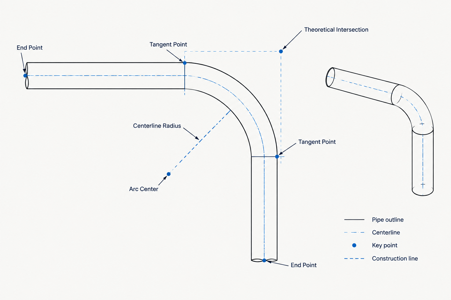
Elbow tangent points connect routing geometry with the physical references used to place fittings and calculate straight-pipe lengths. In piping CAD, the routing corner, fitting connection, and centerline transition may coincide in a simplified view, but they do not always represent the same point.
This guide explains how to distinguish those references, apply them during component placement, and avoid carrying construction geometry into fabrication dimensions.
A piping route may look like a simple sequence of straight centerlines joined by elbows, but several different reference points can exist around each change in direction. The most important are the elbow endpoints, tangent points, arc center, and theoretical intersection of the straight pipe centerlines. Confusing these points can shift dimensions, produce incorrect straight-pipe cut lengths, or create a model that looks connected while its fabrication data is wrong.
Understanding elbow tangent points is especially useful when converting a routing sketch into a detailed model, checking an isometric, or building parametric CAD components. The underlying geometry is straightforward, but it must be combined with verified fitting dimensions rather than treated as a substitute for them.
The main geometric points around an elbow
Consider two straight pipe centerlines that change direction through an elbow. The following references describe different parts of that arrangement:
- Elbow endpoint: The centerline location at an elbow end connection. For a butt-weld elbow, this normally corresponds to the intersection of the pipe centerline and the fitting end plane.
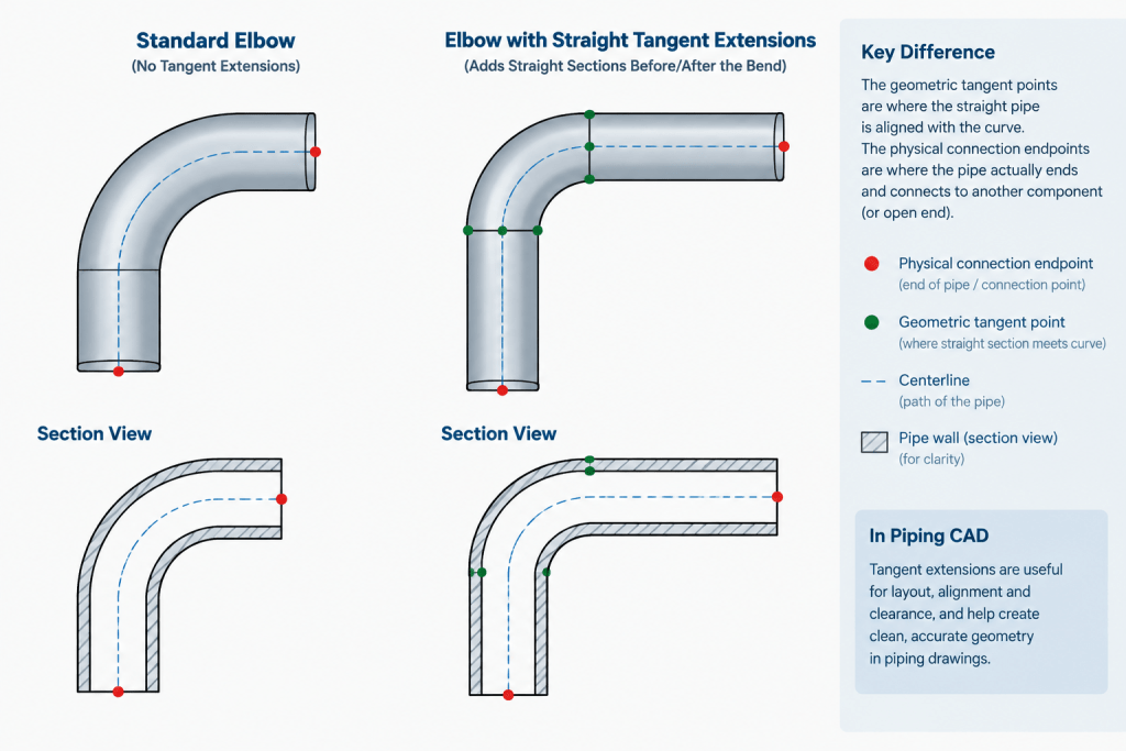
- Tangent point: The point where the curved elbow centerline transitions into a straight centerline. In an ideal circular elbow without an added straight extension, the tangent point and endpoint are commonly represented at the same centerline location.
- Theoretical intersection: The point at which the two straight centerlines would meet if they were extended through the elbow. It is often called the point of intersection or PI. It is a construction reference, not a physical point on the fitting.
- Arc center: The center of the circle used to construct the elbow centerline arc. It is not the same as the theoretical intersection.
- Centerline radius: The radial distance from the arc center to the elbow centerline. This should not be confused with the inside or outside surface radius of the fitting.
These references may be close together in a drawing, but they serve different purposes. The endpoints describe where components connect. The theoretical intersection describes the routing corner. The arc center and radius control the curved geometry.
Why the theoretical intersection is not the elbow center
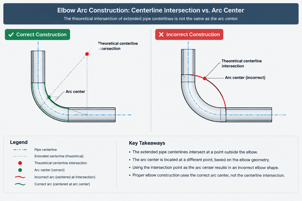
A common drafting mistake is to place the center of the elbow arc at the intersection of the incoming and outgoing pipe centerlines. That construction does not produce an arc tangent to both straight runs.
The theoretical intersection lies outside the elbow centerline arc on the extended straight routing lines. The arc center is offset from those lines and is located by geometric construction. For a symmetrical circular change in direction, the distance from the theoretical intersection to either tangent point is related to the centerline radius and one-half of the direction-change angle. This geometric relationship can be useful for routing calculations, but it does not override a published center-to-end dimension.
Manufactured fittings are selected and detailed using the applicable dimensional reference, project specification, and manufacturer information. Nominal descriptions such as long radius or short radius help classify a fitting, but they should not be used as the only source for fabrication dimensions.
Center-to-end dimensions and tangent points
For a conventional elbow, a center-to-end dimension generally locates an end from a defined fitting center or intersection reference. The exact meaning depends on the fitting type and the dimensional source being used. A CAD library should therefore preserve the reference convention associated with its source data.
For a right-angle elbow represented by two perpendicular straight centerlines, the theoretical intersection provides a convenient routing reference. Each fitting end is offset from that intersection by the applicable center-to-end distance. In an idealized centerline representation, these end locations also act as the tangent points where the straight pipe runs meet the elbow arc.
Other elbow angles require additional care. A drafter should not assume that a dimension used for a right-angle elbow applies unchanged to a different angle. Use the fitting dimensions established for the selected elbow, or use verified manufacturer data for a nonstandard or specialty component.
Do not confuse an end face with the physical edge of a fitting
CAD geometry often uses a single endpoint at the center of an end plane, while the real component has wall thickness, bevels, hubs, sockets, threads, or other end features. The centerline endpoint is therefore a connection reference rather than a complete description of the physical end.
This distinction becomes important when modeling:
- Butt-weld bevel preparation and weld gaps
- Socket-weld insertion and assembly requirements
- Threaded engagement
- Flanged or mechanical end extensions
- Special elbows with tangent extensions
- Fabricated bends that include straight portions beyond the curved region
For an elbow with a built-in tangent extension, the fitting endpoint may be beyond the geometric tangent point of the arc. In that case, the tangent point and connection point must remain separate references in the model.
How the references affect pipe cut lengths
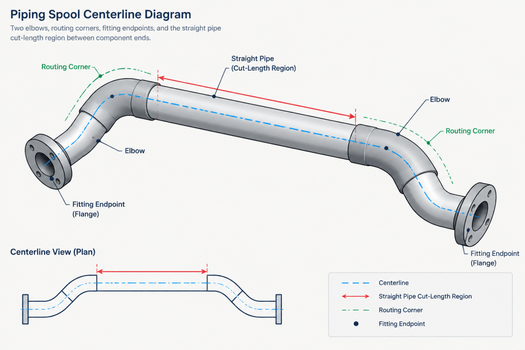
A routing dimension to the theoretical intersection is not automatically a straight-pipe cut length. The elbow occupies part of the distance between routing corners. To obtain a straight segment length, the applicable fitting takeout must be removed from the routing dimension at each end of the segment.
The general workflow is:
- Establish the straight pipe centerlines and their theoretical intersections.
- Select the actual elbow type, size, end connection, and dimensional basis.
- Locate each elbow endpoint using verified center-to-end or equivalent component dimensions.
- Measure the straight pipe between the relevant component endpoints.
- Apply connection-specific requirements such as weld preparation, socket insertion, threaded engagement, or approved fabrication allowances.
Measuring directly from one theoretical intersection to another will normally include space occupied by the fittings. Treating that result as the pipe cut length can make a spool too long.
Reference-point comparison
| Reference | What it represents | Typical CAD use | Common error |
|---|---|---|---|
| Endpoint | Connection location at the fitting end plane | Connectivity, spool dimensions, and component placement | Placing it at the routing corner |
| Tangent point | Transition between curved and straight centerlines | Arc construction and bend geometry | Assuming it always equals the endpoint |
| Theoretical intersection | Intersection of extended straight centerlines | Routing dimensions and layout control | Using it as a physical fitting connection |
| Arc center | Center of the elbow centerline circle | Constructing or checking curved geometry | Confusing it with the theoretical intersection |
| Centerline radius | Radius to the elbow centerline | Geometry checks and bend representation | Using it as an inside or outside surface radius |
A practical CAD construction workflow
1. Build the routing skeleton
Draw the incoming and outgoing pipe centerlines to the intended directions. Their extended intersection defines the routing corner. Keep this construction geometry separate from final component outlines so it can be checked or hidden without changing the model.
2. Identify the component before trimming centerlines
Confirm the elbow angle, end connection, size basis, material specification, and dimensional source. Similar-looking elbows may have different endpoint locations or end details.
3. Place connection ports at verified endpoints
The CAD component ports should represent the actual connection references used by the piping system. Port directions should align with the straight pipe centerlines, and the fitting should have a stable insertion point and orientation convention.
4. Check tangent continuity
The elbow centerline should meet each straight pipe centerline without a visible kink unless the component intentionally contains a non-tangent transition. A connected endpoint alone does not prove that the fitting is correctly oriented.
5. Dimension according to purpose
Use theoretical intersections when communicating routing geometry, endpoints when controlling fabrication interfaces, and overall coordinates when locating the assembly in the plant. Avoid stacking several dimensions that control the same point from different references.
Checks for elbows in a CAD model
- Do the pipe and elbow centerlines meet at the component ports?
- Are the ports located from verified fitting dimensions?
- Is the arc tangent to both straight runs?
- Is the routing corner clearly distinguished from the fitting endpoints?
- Does the elbow angle match the actual direction change?
- Are any tangent extensions modeled as part of the fitting rather than as separate pipe?
- Are cut lengths measured between fabrication references rather than construction points?
- Do the model, isometric dimensions, and bill of materials identify the same elbow type?
Use geometry to check data, not replace it
Geometric construction is valuable for detecting misplaced elbows, broken tangency, and inconsistent routing. It can also help explain why a straight-run dimension differs from a corner-to-corner dimension. However, geometry alone cannot establish the full dimensions of a manufactured fitting.
The reliable approach is to combine clear geometric references with controlled component data. Theoretical intersections define the route, elbow tangent points describe the transition, and verified endpoints control connectivity and fabrication. Keeping those roles separate produces CAD models and isometrics that are easier to review, dimension, and build.
Managing elbow reference points in a CAD workflow
A robust piping model should distinguish between route-control geometry and component-control geometry. The theoretical intersection can remain part of the routing skeleton, while verified fitting endpoints serve as connection ports. This separation allows the route to be edited without redefining what the physical fitting ports represent.
Recommended model information
- Routing node: Identifies the theoretical intersection used to control the change in direction.
- Connection ports: Identify the fitting endpoints used to connect adjoining pipe or components.
- Centerline geometry: Shows the straight and curved portions needed to check alignment and tangency.
- Component identity: Records the selected elbow type and the controlled dimensional basis behind its geometry.
- End-condition information: Distinguishes butt-weld, socket, threaded, flanged, mechanical, or specialty connections where applicable.
Keeping these items separate is particularly helpful in parametric libraries. A route angle or direction may change while the selected component still requires its own verified endpoint locations and end details.
Reviewing dimensions before fabrication release
Dimension review should begin by identifying what each dimension controls. A corner-to-corner routing dimension communicates layout intent, while an endpoint-to-endpoint dimension describes the available straight segment between components. Neither should be silently substituted for the other.
- Trace each displayed dimension to its actual reference points.
- Confirm that component ports coincide with the intended end planes.
- Check that theoretical intersections are not exported as physical connection points.
- Verify that any straight extension belongs to the fitting or pipe segment as intended.
- Compare model geometry, isometric callouts, and fabrication references for consistency.
- Resolve conflicting dimensions before deriving cut lengths or spool information.
If a model displays correct connectivity but produces an unexpected cut length, the first check should be whether the software measured between routing nodes instead of component endpoints. That reference-point error can remain hidden in a visually continuous model.
Frequently asked questions
Is the theoretical intersection the center of an elbow?
No. It is the point where the extended straight pipe centerlines meet. The arc center is a different construction point used to define the curved centerline.
Are an elbow endpoint and tangent point always the same?
They may be represented at the same location for an idealized elbow with no straight extension. They are separate references when the component includes tangent extensions or connection geometry beyond the curved portion.
Can a routing dimension be used directly as a pipe cut length?
Not automatically. A routing dimension may extend between theoretical intersections and include space occupied by fittings. Cut length should be established between the applicable fabrication or connection references, with the relevant end requirements considered.
Why can a connected elbow still show incorrect CAD geometry?
Endpoint connectivity only confirms that selected points meet. The fitting may still be rotated incorrectly, use the wrong port location, or fail to maintain tangency between its curved centerline and the adjoining straight runs.
Which reference should be shown on a piping isometric?
The reference depends on the purpose of the dimension. Theoretical intersections are useful for communicating routing, while endpoints and connection references are needed to control component interfaces and fabrication. The drawing should make the selected reference unambiguous.
Can centerline geometry replace fitting dimensional data?
No. Centerline construction can validate direction, alignment, and tangency, but manufactured fitting geometry must come from the applicable controlled dimensional source and project requirements.