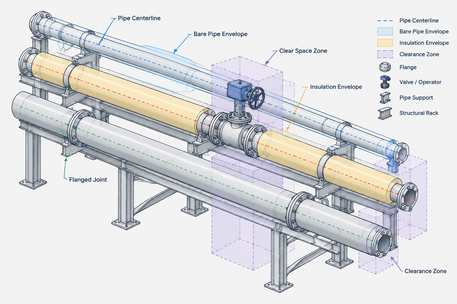
Pipe centerline spacing in CAD should be treated as a coordination decision, not merely a distance between routing lines. The centerlines establish pipe location, while the surrounding physical and functional envelopes determine whether the arrangement can be fabricated, insulated, operated, supported, and maintained.
This guide explains how to evaluate those envelopes without confusing nominal pipe size, outside diameter, finished insulation clearance, or component access. It also shows why stable centerline references remain useful even when local clearances must be checked separately.
Pipe centerline spacing is often treated as a simple routing dimension, but the centerlines are only references. Real clearance is controlled by the outside envelopes of the pipe, insulation, flanges, valves, supports, instruments, and nearby structures. A pair of lines that appears comfortably separated in a plan view may still create a bolt-access problem, insulation conflict, or maintenance obstruction.
A reliable spacing workflow begins by identifying what occupies space around each centerline. The designer can then establish dimensions that remain useful when pipe sizes, schedules, insulation requirements, or inline components change. This is especially important on pipe racks, in equipment areas, and anywhere several services share a limited routing corridor.
Centerline spacing is not the same as clear spacing
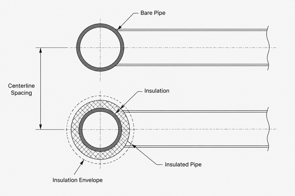
Centerline spacing is the perpendicular distance between two pipe axes. Clear spacing is the shortest free distance between the relevant outside envelopes. These terms should not be used interchangeably.
For two parallel bare pipes, clear spacing depends on centerline spacing and the outside radius of each pipe. Pipe schedule may change the bore and wall thickness without changing the standard outside diameter for a given nominal pipe size, so a schedule change does not necessarily alter the bare-pipe envelope. A nominal size change, however, usually does.
The calculation becomes more involved when either line has insulation, heat tracing, jacketing, flanges, valves, branch connections, supports, or expected movement. In those cases, the controlling envelope may be much larger than the pipe itself.
Choose the correct envelope for each line
Before setting a spacing dimension, decide which physical condition must be kept clear. Different parts of the same line can have different controlling envelopes.
| Envelope | What it represents | Typical use in spacing checks |
|---|---|---|
| Bare pipe | Pipe outside diameter without external coverings | Preliminary routing where no insulation or special coating envelope applies |
| Insulated pipe | Pipe, insulation, protective jacket, and any modeled external allowance | Operating clearance and coordination with adjacent lines or steel |
| Flanged joint | Flange outside envelope, bolts, nuts, gasketed joint, and required tool approach | Checking local congestion and assembly access |
| Valve or specialty item | Body, bonnet, operator, actuator, accessories, and removal path | Maintenance and operability review |
| Support assembly | Shoe, clamp, guide, hanger, bracket, or other support hardware | Coordination with adjacent lines and structural framing |
| Movement envelope | Range occupied as the line expands, contracts, vibrates, or is displaced | Hot-position and dynamic clearance review |
A single project-wide centerline spacing value may be useful for early layout, but it should not replace local checks at large components. Flanges and valve operators commonly govern spacing even when the straight pipe runs do not conflict.
Factors that commonly control pipe spacing
Insulation and external coverings
Insulation must be evaluated as an outside envelope, not as information stored only in a line list. The relevant build-up may include insulation, jacketing, tracing, protective coatings, weather barriers, and removable insulation covers. The designer should use approved project data rather than assuming that every line of the same nominal size has the same finished diameter.
Clearance may also be needed so insulation can be installed, sealed, inspected, and repaired. Two finished insulation jackets that merely touch in the model do not provide usable installation space.
Flanges and bolting
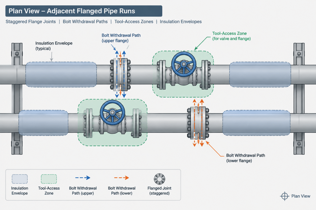
Flange outside diameter can extend well beyond the bare pipe envelope. A geometric no-clash check is only the first step. Bolts may need axial withdrawal space, and nuts require room for tools and tightening operations. Nearby pipe, steel, cable tray, or insulation can obstruct this work even when none of the modeled solids overlap.
Opposing flanges on adjacent lines can create concentrated congestion. Where practical, staggering flanged joints or inline equipment along the routing direction may reduce the required rack width and improve access.
Valves and operators
The valve body is not always the controlling object. Handwheels, levers, gear operators, stems, actuators, limit switches, tubing, and local accessories can extend into adjacent pipe lanes. Their orientation also affects whether spacing is acceptable.
CAD models should distinguish between a compact symbolic representation and the actual component envelope. Vendor information may be required before a final access decision can be made. Until verified information is available, the model should identify the item as provisional rather than presenting an assumed envelope as final.
Branches, drains, vents, and instruments
Branch fittings and small connections can project into the space between otherwise parallel lines. Instrument taps, root valves, manifolds, vents, drains, and sample connections may also require access from a specific direction. These details are easily missed when spacing is reviewed only in a pipe-rack plan.
Supports and structural interfaces
Pipe shoes, clamps, guides, line stops, trunnions, and hanger hardware can be wider than the pipe or insulation. Supports also need suitable bearing or attachment locations on the structure. A line may fit between neighboring pipes but still be impossible to support without interfering with their shoes or support steel.
Thermal and mechanical movement
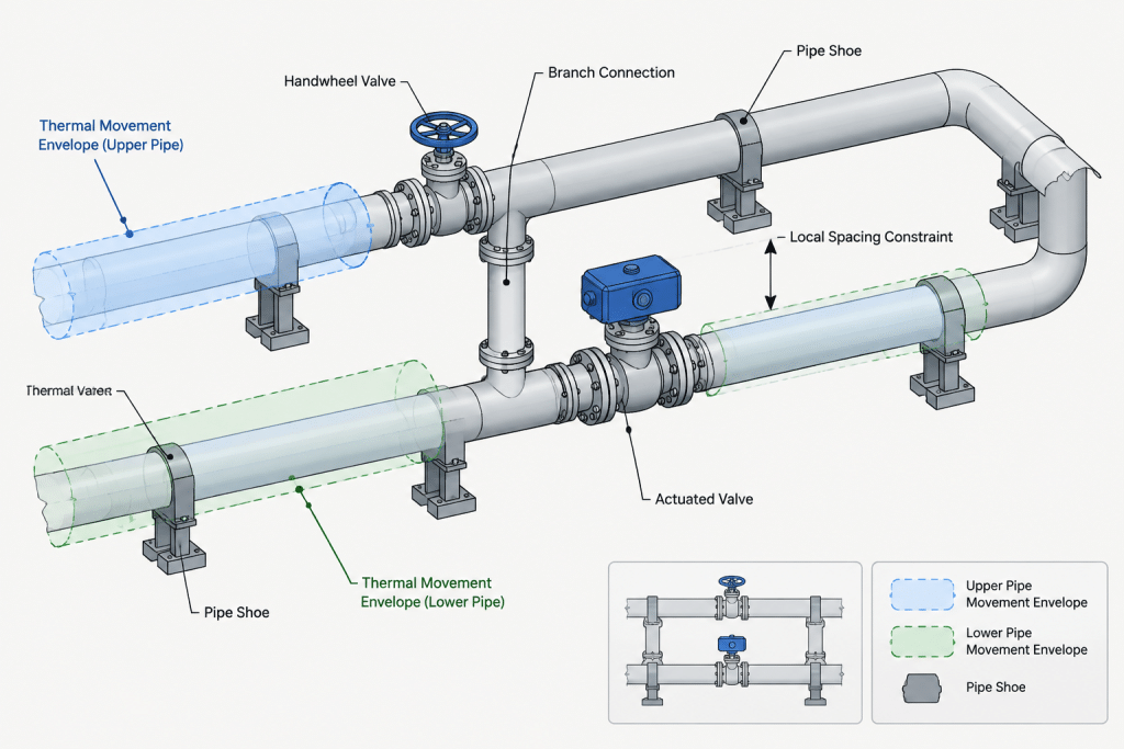
Spacing established in the modeled installation position may not remain adequate during operation. Thermal expansion can move a line laterally or axially, while guides, anchors, and line stops control how that movement develops. Vibration and equipment nozzle displacement may add other operating positions.
The clearance review should therefore consider the required movement cases supplied by the responsible engineering discipline. CAD should communicate the relevant cold and operating envelopes clearly rather than silently enlarging geometry without explanation.
A practical CAD spacing workflow
- Collect governing inputs. Review the line list, piping material specification, insulation requirements, equipment information, support criteria, layout philosophy, and project clearance rules.
- Classify the routing corridor. Identify whether the lines are on a rack, at grade, overhead, in a trench, near equipment, or within an access platform. Each location introduces different constraints.
- Route with stable centerline references. Use grids, rack column lines, equipment coordinates, or designated pipe lanes. Avoid building the layout from a chain of incidental clearances.
- Apply realistic outside envelopes. Show insulation and major component extents where they affect coordination. Use clearly labeled placeholders when verified component dimensions are unavailable.
- Check local enlargements. Review flanges, valves, strainers, branch fittings, instruments, and support hardware rather than inspecting straight pipe alone.
- Review installation and maintenance paths. Consider bolt withdrawal, valve operation, actuator removal, insulation work, weld access, and component replacement.
- Evaluate movement. Compare adjacent lines and structures against applicable operating or displacement envelopes.
- Record the basis. Note which spacing criteria and component data were used, and flag unresolved vendor or engineering inputs.
Why automatic clash detection is not enough
Clash detection generally reports intersecting geometry or separations below a configured threshold. It does not automatically understand why a clearance is needed. A model can be clash-free while remaining difficult to fabricate, insulate, operate, or maintain.
Examples of non-clash problems include a handwheel that cannot be reached, a bolt that cannot be withdrawn, an actuator blocked from removal, or insulation trapped between two lines. These conditions require rule-based review and human judgment in addition to geometric checking.
Dimensioning centerlines on drawings
Centerline dimensions are usually more stable than dimensions to pipe surfaces because they remain tied to routing geometry. Drawings should reference suitable datums such as structural grids, equipment centerlines, rack lines, or established coordinates.
Do not dimension every pipe from the outside of its neighbor. Such chained dimensions can make the layout dependent on nominal size, insulation, or component changes. A clearer method is to locate important centerlines from a common datum and provide selected spacing or clearance dimensions where they communicate a specific requirement.
If a required dimension represents finished insulation clearance rather than centerline spacing, label that basis explicitly. Similar care is needed when the dimension applies only at a flange, valve, support, or maintenance envelope.
Common spacing mistakes
- Using nominal pipe size as though it were the actual outside diameter.
- Checking straight pipe while ignoring larger flange and valve envelopes.
- Modeling insulation graphically but excluding it from clash and clearance reviews.
- Assuming a generic valve symbol represents the final operator or actuator size.
- Placing adjacent flanges at the same station without reviewing bolting and tool access.
- Ignoring support shoes, guides, clamps, or hanger rods.
- Checking only the installation position when thermal movement is expected.
- Using surface-to-surface dimension chains that become invalid after size changes.
- Treating a no-clash result as confirmation of constructability and maintainability.
Final review questions
Before releasing a coordinated layout, reviewers should ask what physically controls each critical spacing. Is it bare pipe, finished insulation, a flange, an operator, a support, or an operating movement envelope? They should also confirm whether provisional components are visibly identified and whether the drawing dimensions are tied to stable references.
Good pipe centerline spacing in CAD is not simply wide spacing. It is deliberate spacing based on verified envelopes, access needs, support arrangements, and operating behavior. That approach produces layouts that are easier to coordinate and less likely to require late changes during fabrication or installation.
Separate the routing dimension from the clearance requirement
A useful CAD layout records two different ideas: where the pipe axis belongs and what must remain clear around the pipe. The centerline is normally the stable routing reference. The clearance requirement may vary along that centerline as insulation, joints, components, supports, branches, and movement conditions change.
This distinction helps designers respond to revisions. If a component envelope changes, the local clearance can be reviewed without automatically rebuilding every routing dimension. If the centerline must move, its relationship to the controlling grid, equipment datum, or rack reference remains visible.
Document assumptions and unresolved inputs
Spacing decisions are only as reliable as the information behind them. When insulation build-up, valve operator geometry, support details, or vendor dimensions remain unverified, the model and associated review records should identify that status clearly. A placeholder can support early coordination, but it should not be mistaken for approved component geometry.
- Identify the controlling envelope. State whether the check is based on bare pipe, finished insulation, a flange, an operator, a support, or movement.
- Record the data status. Distinguish verified information from preliminary or generic geometry.
- Describe the access purpose. Note whether space is reserved for operation, bolting, insulation work, inspection, or component removal.
- Assign unresolved checks. Make clear which discipline or supplier input is still required.
- Review affected views. Confirm the condition in plan, elevation, section, and model views as appropriate.
Use local checks instead of unnecessary global spacing
Increasing the separation between every line can consume routing space without resolving the actual access problem. A more effective approach is to locate the controlling obstruction and evaluate options such as changing component orientation, staggering enlarged items, adjusting support placement, or relocating a specific centerline.
Any adjustment should still be reviewed against piping design requirements, structural interfaces, equipment connections, movement needs, and project-specific criteria. CAD geometry communicates the arrangement, but it does not replace the engineering decisions that establish acceptable clearance.
Frequently asked questions
What is the difference between pipe centerline spacing and clear spacing?
Centerline spacing is measured between pipe axes. Clear spacing is the free distance between the outside envelopes being evaluated, such as bare pipe surfaces, finished insulation, flanges, valve operators, or supports.
Does a pipe schedule change always require different centerline spacing?
Not necessarily. For a given nominal pipe size, a schedule change may alter the wall and bore without changing the standard outside diameter. Spacing must still be reviewed if the service, insulation, component selection, support arrangement, or movement requirement changes.
Should insulation be included in CAD clearance checks?
Yes, when insulation or its external covering affects coordination. The relevant envelope may include the pipe covering, jacket, tracing, removable sections, and the working space needed for installation or repair. Approved project information should define the applicable build-up.
Why can adjacent flanges be a problem even when they do not clash?
Flanges can leave inadequate room for bolts, nuts, tools, insulation, or joint assembly. A geometric gap therefore does not prove that the connection can be installed or serviced.
How should provisional valve geometry be handled?
Use a clearly identified placeholder based on available information and flag it for later verification. The final review should consider the body, operator, stem, actuator, accessories, operating reach, and removal path.
Is automatic clash detection sufficient for pipe spacing approval?
No. Clash detection can identify intersecting geometry or configured proximity conditions, but it does not inherently assess operability, tool access, insulation work, support feasibility, or maintenance procedures.
What should pipe centerlines be dimensioned from?
Use stable project references such as structural grids, rack lines, equipment centerlines, or established coordinates. Surface-based dimension chains are more vulnerable to pipe size, insulation, and component changes.
When should movement envelopes be reviewed?
Review them whenever engineering information indicates that thermal displacement, vibration, nozzle movement, or another operating condition can change the occupied space. The applicable cases should come from the responsible engineering discipline.