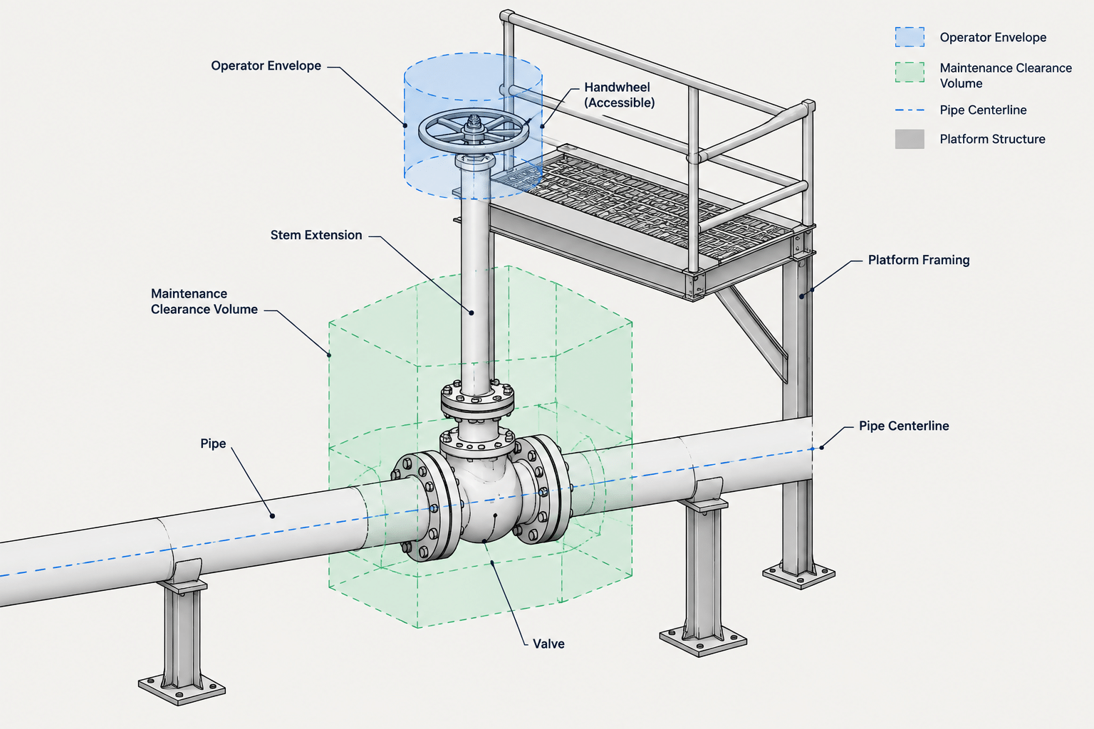
Valve operator extensions and chain wheels can make an otherwise inaccessible valve operable, but they also add movement, clearance, support, and maintenance requirements to the piping layout. Effective CAD coordination must consider the complete path from the valve stem or gearbox to the location where personnel will operate the device.
This guide explains how to represent these arrangements without confusing conceptual geometry with verified equipment details. It also highlights the interfaces among piping, structural work, access platforms, vendor components, and operating procedures.
A valve may fit within a piping model while its operator remains difficult or unsafe to reach. Elevated pipe racks, crowded equipment areas, insulated lines, pits, and guarded process zones can place a handwheel or lever beyond practical operating access. Valve operator extensions, chain wheels, and remote operating systems address that problem, but they also introduce geometry and interfaces that must be coordinated in CAD.
These devices should not be treated as decorative additions to a valve block. An extension changes the operating point, may require guides or supports, and can create new clashes during travel or maintenance. The designer must distinguish the pressure-containing valve from the mechanism used to operate it and must verify the complete arrangement against vendor information and project requirements.
What Is a Valve Operator Extension?
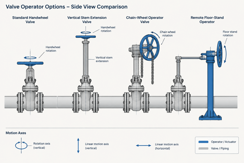
A valve operator extension transfers motion from an accessible operating point to the valve stem, gearbox, or actuator. The form of the extension depends on the valve, operating motion, location, and selected equipment.
Common arrangements include:
- Stem extension: A rigid member raises or relocates the operating point while generally remaining aligned with the valve stem.
- Extended bonnet or stem arrangement: A valve configuration in which the manufacturer provides additional separation between the pressure boundary and the operator.
- Chain wheel: A wheel operated by a hanging loop of chain, often used where a conventional handwheel is above normal reach.
- Remote mechanical operator: A system using shafts, joints, gearboxes, or similar components to operate a valve from another position.
- Floor stand or pedestal operator: An operating station mounted at a floor, platform, or deck and mechanically connected to a valve below or beyond the operating surface.
These terms are not automatically interchangeable. A simple stem extension, for example, does not necessarily solve an offset-access problem. A chain wheel changes where the operator stands, but it also introduces a hanging chain path that must remain clear.
Start with the Operating Requirement
Before selecting or drawing an extension, identify why the standard operator location is unsuitable. The reason affects the type of solution and the CAD information needed.
- Is the valve above a platform or walkway?
- Is it below a floor, inside a pit, or behind a barrier?
- Would hot surfaces, insulation, rotating equipment, or process exposure make local operation undesirable?
- Must the valve be operated frequently, or is access mainly required for isolation and maintenance?
- Does operation require a continuous line of action, or can the motion change direction through a gearbox or joint?
- Will the valve, piping, or supporting structure move during operation?
The P&ID may indicate the valve type and actuation method, but it usually does not define the complete physical access arrangement. The piping model, structural model, operating philosophy, and vendor data must therefore be reviewed together.
Separate Valve Geometry from Operator Geometry
A useful CAD workflow treats the valve body, valve operator, and extension assembly as related but distinct items. This makes it easier to replace a valve model, revise an extension length, or change an access concept without rebuilding the entire assembly.
The valve body controls the process connection geometry, including end connections and face-to-face length. The operator introduces additional envelopes associated with the stem, gearbox, actuator, lever, handwheel, chain guide, or remote drive. The extension connects those systems but may also depend on structural supports that are outside the piping component itself.
Model connection points or reference axes where practical. Useful references include the pipe centerline, valve stem axis, operator input axis, floor or platform elevation, and intended standing position. Avoid locating an extension only by eye in an orthographic view; small angular errors can become significant over a long shaft.
CAD Considerations by Operator Type
| Arrangement | Important geometry | Typical coordination concerns |
|---|---|---|
| Vertical stem extension | Stem axis, coupling, guides, upper operator elevation | Alignment, insulation clearance, lateral stability, overhead space |
| Chain wheel | Wheel envelope, chain loop, hanging path, operator position | Snag hazards, adjacent valves, walkways, equipment and handrails |
| Remote shaft operator | Shaft centerline, joints, gearboxes, support points | Angular alignment, structural interfaces, shaft movement and maintenance |
| Floor stand or pedestal | Stand location, input shaft, deck penetration, connection to valve | Floor framing, mounting details, weather or process exposure, access below |
| Extended lever | Lever length and swept area | Full operating arc, pinch points, nearby piping and removable access |
Stem Extensions
A rigid stem extension must follow the intended operating axis unless the selected mechanism is specifically designed to redirect motion. In CAD, check the extension as a complete assembly rather than as a line between two points. Couplings, guide brackets, protective tubes, and the upper operator can control the required space.
The designer should also determine whether the valve stem rises, rotates, or combines motions during operation. A model that shows only the normal operating position may miss the maximum vertical or rotational envelope. Manufacturer information is necessary because valves with similar body geometry can have different stem and operator behavior.
Chain Wheels
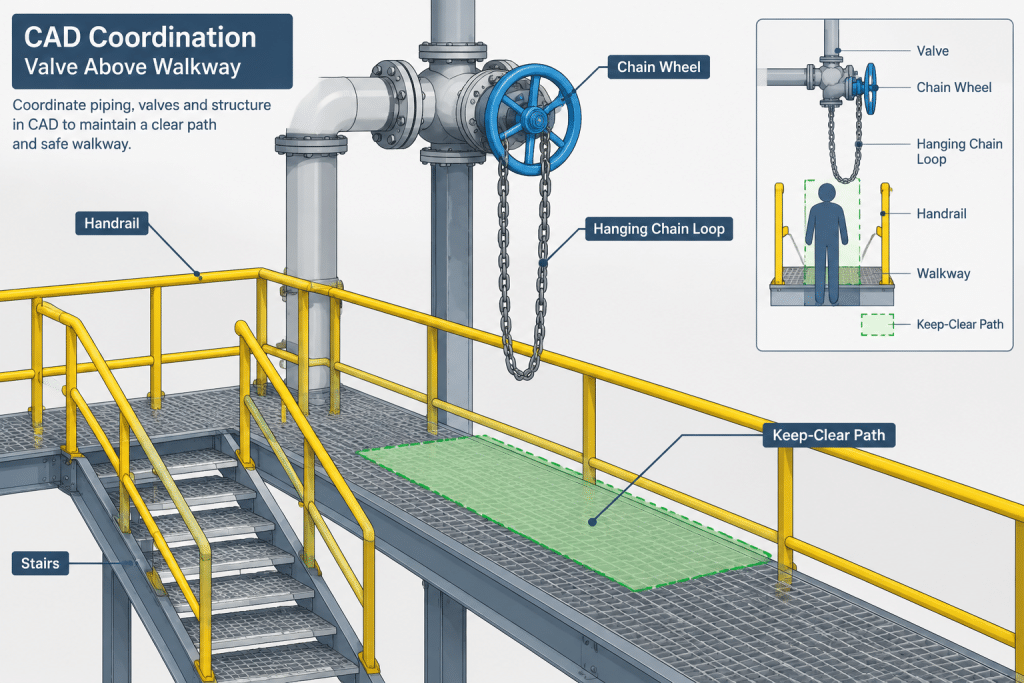
A chain wheel is not represented adequately by enlarging the handwheel symbol. The chain loop occupies vertical space and can swing or twist. Its lower operating portion should be coordinated with the intended standing area while remaining clear of stairs, handrails, access routes, nearby equipment, and other hanging chains.
In congested areas, identify which chain belongs to which valve. Drawing labels, operator tags, or a simple chain-path representation can prevent ambiguity. The final chain length and termination arrangement should be based on approved project or vendor information rather than estimated directly from a schematic model.
Remote Shafts and Floor Stands
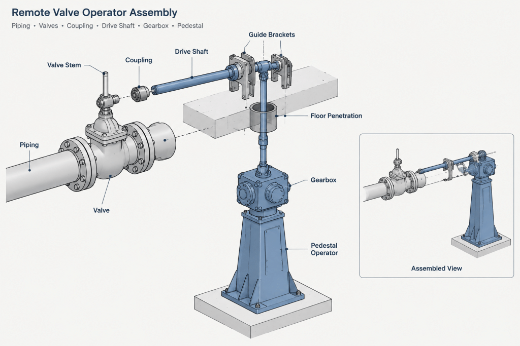
Remote mechanical systems create interfaces between piping, mechanical equipment, and structural design. A floor stand may require a mounting plate, opening, sleeve, or framing provision. A shaft may require intermediate guides and sufficient clearance for couplings or universal joints.
Do not assume that a shaft can accommodate any offset or angular change. The permissible geometry depends on the selected mechanism. Show the intended routing and support concept in CAD, but verify detailed limits with the responsible supplier or engineer.
Model the Operating and Maintenance Envelopes
The visible components represent only part of the required space. The model should account for both normal operation and foreseeable maintenance activity.
- Operating envelope: Handwheel rotation, lever sweep, chain movement, actuator travel, or rising-stem travel.
- Personnel envelope: The position from which an operator can identify and manipulate the correct valve.
- Removal envelope: Space for disconnecting couplings, lifting an operator, withdrawing a shaft, or removing a gearbox cover.
- Adjustment envelope: Access to fasteners, stops, lubrication points, or position indicators.
- Adjacent movement: Thermal pipe displacement, equipment vibration, or structural movement that could misalign a rigid extension.
CAD clearance volumes can be placed on a dedicated review layer or assigned a nonfabrication status. They should be distinguishable from permanent material so they are not accidentally included in bills of material or issued as physical components.
Coordinate Supports Without Restraining the Pipe Incorrectly
Long extension shafts may need lateral guidance, but attaching a guide to a pipe support or nearby steel is not automatically acceptable. The valve and pipe may move relative to the structure. A rigidly supported shaft could bind, transmit unwanted loads to the valve stem, or cease to align after thermal movement.
Clarify which discipline owns each bracket, guide, pedestal, or penetration. The piping drawing can show the required location and interface, while a structural or vendor detail defines the actual attachment. If relative movement is expected, flag it for mechanical review rather than solving it with an unverified CAD detail.
How to Document the Arrangement
The level of drawing detail should match the project stage. During layout, a simplified envelope and operating point may be enough to reserve space. Fabrication or installation documents usually need clearer component identification and interface information.
Useful documentation may include:
- Valve tag and service identification.
- Operator type and intended operating location.
- Stem or drive-shaft axis.
- Platform, floor, or grade reference elevation.
- Required structural interface or support location.
- Chain path or lever operating sweep.
- Vendor-document reference when available.
- Notes identifying dimensions that remain subject to supplier confirmation.
Avoid defining a custom extension length solely from a generic valve symbol. The final dimension may depend on the actual valve stem, gearbox input, coupling, bonnet, insulation, platform construction, and mounting hardware.
Practical CAD Review Workflow
- Confirm the valve and operating intent. Check the valve type, normal accessibility, actuation method, and expected frequency of operation.
- Locate the real operator position. Identify where personnel will stand and whether the location remains accessible after all platforms, handrails, and equipment are installed.
- Establish reference axes. Use the valve stem axis, shaft axis, and structural elevations rather than approximate visual alignment.
- Place the complete envelope. Include the wheel, chain, lever, gearbox, couplings, guides, and relevant travel.
- Check piping movement. Determine whether thermal or equipment movement could change alignment with a structure-mounted operator.
- Review maintenance access. Verify that components can be disconnected and removed without dismantling unrelated piping.
- Assign interfaces. Identify responsibility for structural brackets, floor openings, pedestals, guards, and vendor-supplied parts.
- Update drawings and material data. Ensure the isometric, arrangement drawing, model, valve data, and bill of material describe a consistent solution.
Common Drafting Mistakes
- Showing an extension as a straight line without modeling its couplings, guides, or operator.
- Locating the handwheel access point without checking the operator’s standing space.
- Allowing chain loops to overlap stairs, walkways, instruments, or other chains.
- Ignoring rising-stem travel because the valve is modeled only in one position.
- Supporting a remote shaft from fixed steel without considering pipe movement.
- Including conceptual support geometry in the piping bill of material.
- Using a generic valve block as the source of final extension dimensions.
- Failing to identify whether the extension is vendor supplied, field fabricated, or designed by another discipline.
Final Review Principle
A valve operator extension is an access system, not merely a longer stem. A reliable CAD arrangement connects the valve’s actual motion to a usable operating location while accounting for supports, movement, personnel access, and maintenance. Generic geometry is useful for early coordination, but final dimensions and mechanical details must be verified against the selected valve, operator, vendor information, and project requirements.
Match CAD Detail to the Design Decision
The model should communicate what has been selected, what is being reserved, and what still requires confirmation. Early layout geometry may establish an operator location and clearance envelope without defining the final mechanism. As equipment information becomes available, that placeholder should be replaced or supplemented with verified interfaces, movement, supports, and access requirements.
Conceptual Layout Representation
During arrangement development, show enough geometry to test accessibility and detect major conflicts. Clearly identify simplified shafts, chain paths, support locations, and clearance volumes as conceptual so they are not mistaken for fabrication-ready parts.
Vendor-Coordinated Representation
Once the valve and operator arrangement are defined, coordinate the actual connection axes, coupling locations, operating motion, and required support interfaces. Differences between a generic valve model and the selected equipment can affect alignment even when the valve body appears to fit the same piping space.
Installation Review
Before issue for installation, review the operator system as an assembled and maintainable arrangement. Confirm that construction sequencing, platform completion, insulation, guards, and nearby equipment will not block access to couplings, chains, fasteners, indicators, or removable components.
Questions for a Multidiscipline Model Review
- Operations: Can personnel identify and operate the correct valve from the intended standing location?
- Piping: Does the arrangement remain aligned as the valve and connected pipe move?
- Structural: Are pedestals, brackets, openings, and guide locations coordinated with the supporting construction?
- Mechanical or vendor: Is the proposed motion transfer compatible with the selected valve and operator?
- Maintenance: Can the extension, gearbox, chain wheel, or shaft components be inspected and removed?
- CAD administration: Are clearance objects and conceptual supports excluded from fabricated material reporting?
The review is complete only when the accessible operating point and the mechanical path back to the valve are both understood. Resolving one without the other can leave an arrangement that looks coordinated in the model but cannot be operated or maintained as intended.
Frequently Asked Questions
Is a valve stem extension the same as a chain wheel?
No. A stem extension relocates the operating input through a rigid mechanical connection, while a chain wheel allows a handwheel to be operated using a hanging chain loop. Each arrangement creates different motion, clearance, support, and access considerations.
Should the chain loop be modeled in piping CAD?
Yes, at least as a coordination path or envelope. The hanging chain can interfere with walkways, handrails, equipment, instruments, and neighboring valve chains even when the wheel itself is clear.
Can a generic valve model define the final extension geometry?
No. Generic geometry can reserve space during layout, but final connections and operating behavior depend on the selected valve, gearbox, stem arrangement, couplings, mounting hardware, and supplier information.
Who is responsible for extension supports and floor stands?
Responsibility depends on the project and procurement arrangement. The piping model should identify the required location and interface, while the responsible piping, structural, mechanical, or vendor party develops and verifies the attachment details.
Why must pipe movement be checked for a remote operator?
A valve attached to moving piping may shift relative to a structure-mounted shaft, guide, or pedestal. If that relative movement is not accommodated, the mechanism can become misaligned or transfer unintended loads to the valve.
What should be shown when vendor information is unavailable?
Show the design intent, reference axes, proposed operating location, conceptual routing, and clearance envelopes. Mark unverified components and interfaces clearly so placeholder geometry is not treated as approved fabrication information.