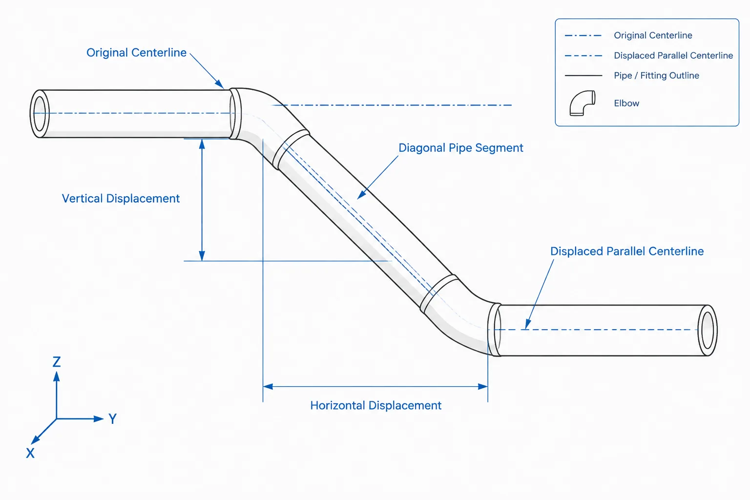
Rolling offsets in piping CAD require more than drawing a diagonal line between displaced pipe runs. The model must represent the combined lateral and vertical movement, the actual centerline path, and the orientation of each elbow. Confusing a projected distance with true geometry can produce incorrect fitting placement, spool dimensions, or fabrication information.
This guide explains how true offset, travel, advance, roll direction, and fitting reference points work together. It also outlines a practical method for checking the route in plan, elevation, isometric, and model views before releasing drawings or fabrication data.
A rolling offset allows a pipe run to move in two perpendicular directions at the same time. Instead of shifting only left or right, or only up or down, the offset crosses both plan and elevation. This geometry is common where piping must pass around structural steel, other lines, equipment, cable tray, or ductwork.
Rolling offsets can look simple in a 3D model but become difficult to communicate on plans and isometrics. The designer must distinguish coordinate displacement from actual pipe length, orient the elbows correctly, and avoid treating a projected view as the true geometry. A reliable workflow begins by defining the terms and reference points used in the calculation.
Simple Offsets vs. Rolling Offsets
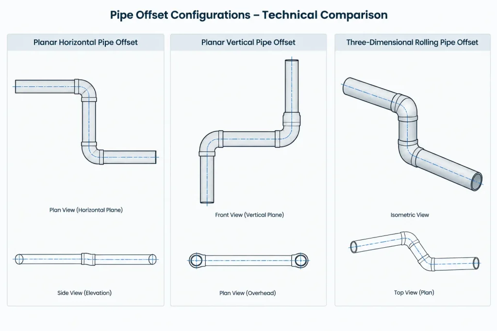
A simple offset lies in one plane. For example, two elbows may shift a horizontal run sideways while the entire arrangement remains at one elevation. The same concept can create a vertical offset within an elevation view.
A rolling offset is not confined to one principal drawing plane. Between the start and end of the offset, the pipe changes position along two perpendicular offset axes. The diagonal section therefore appears foreshortened in both plan and elevation unless one view is aligned with its actual plane.
| Geometry | Displacement | Drafting implication |
|---|---|---|
| Simple offset | Change along one offset axis | One principal view may show the true offset geometry |
| Rolling offset | Changes along two perpendicular offset axes | Plan and elevation usually show projections rather than true length |
| Compound route | Multiple directional changes that may use different bend angles or planes | Should not automatically be treated as a standard two-elbow rolling offset |
The term rolling describes the rotation of the offset plane around the axis of the original pipe run. Two elbows may have the same nominal bend angle as a simple offset, but their plane is rotated to produce both lateral and vertical movement.
Key Rolling Offset Terms
Component offsets
The component offsets are the two perpendicular displacements that move the pipe from its original centerline to its new centerline. They might represent a horizontal shift and an elevation change, but the applicable axes depend on the project coordinate system and route direction.
Use signed coordinate differences during CAD calculations. Signs preserve direction and help determine whether the line rises, drops, moves east, or moves west. Absolute values may be sufficient for length calculations, but they are not sufficient for establishing orientation.
True offset
The true offset is the direct perpendicular separation between the original and displaced parallel pipe centerlines. It combines the two component offsets:
True offset = √[(first component offset)² + (second component offset)²]
This is a geometric centerline value. It is not automatically a pipe cut length and does not include fitting dimensions.
Travel
In a conventional two-elbow offset, travel commonly refers to the diagonal centerline distance between defined theoretical intersection points. If the elbows use the same deflection angle and the geometry is symmetrical, travel can be related to true offset by:
Travel = true offset / sin(elbow deflection angle)
Terminology varies among shops, software systems, and field references. Some users apply words such as travel, diagonal, run, or advance differently. A drawing or calculation sheet should identify its reference points instead of relying on the term alone.
Advance
Advance is the distance consumed along the original run direction while the pipe makes the offset. For the standard two-elbow arrangement:
Advance = true offset / tan(elbow deflection angle)
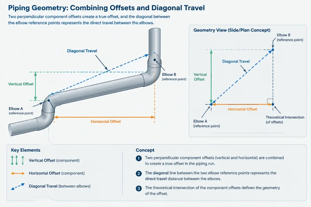
Advance is important when checking whether an offset fits between equipment nozzles, branches, supports, or other fixed features. A route may have enough clearance perpendicular to the pipe but insufficient straight-line space to complete the offset.
Roll angle
The roll angle identifies the rotation of the offset plane about the original pipe axis. It can be derived from the two perpendicular component offsets, but the result depends on which axis is used as the angular origin and which rotation direction is considered positive.
For that reason, an unlabeled angle is risky. A useful fabrication document pairs the angle with directional information, coordinate changes, or endpoint elevations. A 3D model should also preserve the actual elbow port directions rather than storing only a generic rotation value.
Why Projected CAD Measurements Can Be Misleading
A plan view shows the horizontal projection of a rolling offset. An elevation shows another projection. Neither projected diagonal is necessarily the actual centerline length of the sloped pipe segment.
Common errors include:
- Measuring the diagonal in plan and using it as a cut length.
- Calculating from an elevation while ignoring the lateral displacement.
- Snapping to fitting outlines instead of component ports or centerline reference points.
- Using outside surfaces where the calculation requires centerlines.
- Rounding coordinates before the geometry has been solved.
- Mirroring an offset without checking whether the elbow orientations and slope direction also changed.
When accurate 3D centerlines are available, the safest geometric check is the three-dimensional distance between the defined endpoints. For coordinate differences along three axes, the segment length is:
Length = √(ΔX² + ΔY² + ΔZ²)

This equation checks the direct distance between points. It does not account for elbow takeout, socket insertion, threaded makeup, weld preparation, or other connection-specific fabrication requirements.
A Practical CAD Modeling Workflow
- Confirm the fixed endpoints. Establish the upstream and downstream centerlines, elevations, coordinates, and route directions. Determine whether both lines are parallel; the standard two-elbow method assumes they are.
- Identify the two offset components. Separate the displacement perpendicular to the original run into the applicable project axes.
- Calculate the true offset. Combine the perpendicular components rather than using either projected value by itself.
- Select the intended elbow geometry. Use the project piping specification and approved component data. Do not select an angle only because it produces convenient geometry.
- Check the required advance. Verify that the offset fits between nearby branches, valves, supports, welds, and equipment interfaces.
- Construct the diagonal centerline. Connect verified elbow reference points or ports. Avoid placing fittings by eye in an isometric view.
- Orient both elbows. Confirm that the outlet vector of the first elbow aligns with the inlet vector of the second. Also verify that the final outlet is collinear with the downstream run.
- Apply actual component dimensions. Replace conceptual elbows with the correct catalog geometry or verified project dimensions before deriving spool lengths.
- Review in multiple views. Use plan, elevation, section, and 3D views to check direction, clearance, and accessibility.
Travel Is Not the Same as Pipe Cut Length
Rolling offset calculations generally solve centerline geometry. Fabrication requires connection-to-connection dimensions and component-specific deductions or allowances.
For a butt-welded arrangement, a straight pipe cut length may be based on the distance between elbow weld-end reference points after the elbows are positioned. If a calculation instead uses theoretical intersections of fitting centerlines, the applicable elbow takeouts must be considered. Other connection types may introduce insertion, engagement, end-gap, or makeup requirements.
Never apply a generic fitting deduction without confirming what points the CAD system, catalog, or calculation uses. Center-to-end, tangent, face, weld end, socket bottom, and component port are not interchangeable references.
How to Document a Rolling Offset
A fabrication isometric should provide enough information to reconstruct the offset without scaling the drawing. Depending on project practice, useful controls include:
- Endpoint coordinates or locating dimensions.
- Centerline elevations at both ends.
- Horizontal component displacement.
- Flow direction and line identification.
- Elbow type and nominal angle through the component callout or bill of material.
- Centerline dimensions tied to clearly defined reference points.
- Weld locations, spool boundaries, and field-fit provisions where applicable.
- A supplemental section or orientation detail when the isometric is ambiguous.
Avoid overdimensioning the same endpoint through several independent dimension chains. Coordinates, component offsets, travel, and advance are mathematically related. If all are presented as controlling dimensions, normal rounding can create conflicts. Select a clear set of controlling values and treat the rest as reference information when needed.
Review Checks Before Release
- Are the upstream and downstream centerlines truly parallel?
- Were both perpendicular offset components included?
- Does the diagonal route connect the intended fitting ports?
- Are the elbows rolled in the correct direction rather than mirrored?
- Does the line rise or fall as required by the process and drainage intent?
- Were actual fitting dimensions used for spool or cut-length calculations?
- Is there clearance for the pipe outside diameter, insulation, flanges, weld access, and nearby systems?
- Can the assembly be fabricated, transported, installed, and connected?
- Do the isometric dimensions agree with the coordinated 3D model?
A rolling offset is ultimately a three-dimensional vector problem combined with real fitting geometry. Keeping true offset, travel, advance, and cut length separate makes the route easier to calculate, model, review, and fabricate. The most dependable CAD workflow controls endpoints and component ports first, then derives the necessary lengths and orientation information from that verified geometry.
Model Geometry and Fabrication Geometry Must Agree
A mathematically correct centerline does not by itself confirm that a rolling offset is ready for fabrication. The model must also use the intended elbow geometry, connection references, and project coordinate system. Conceptual routing can establish feasibility, but spool development should wait until verified components replace generic placeholders.
Control the endpoints before controlling the diagonal
The most stable CAD approach begins with fixed upstream and downstream centerlines. Their coordinates, elevations, and direction vectors define the required displacement. The diagonal section should then be derived from those controls rather than adjusted visually until the elbows appear connected.
This distinction matters when a route is revised. If the endpoints remain authoritative, the true offset and related geometry can be recalculated consistently. If the diagonal was placed by eye, a small endpoint change may leave disconnected ports, unintended slope, or elbows that no longer share the same offset plane.
Use vectors to review elbow orientation
Elbow orientation can be checked by comparing the direction entering the fitting, the direction leaving it, and the direction of the adjoining centerline. The first elbow must turn toward the diagonal segment, while the second must turn from that segment into the displaced parallel run.
A mirrored arrangement may retain similar-looking projected geometry while reversing the rise, drop, or lateral movement. Directional vectors and signed coordinate differences expose this error more reliably than an isometric screenshot.
Separate design controls from reported references
Drawings and calculation sheets should identify which values control the route and which are reported only for checking. Endpoint coordinates, centerline dimensions, component offsets, travel, and advance describe related geometry. Treating every derived value as independently controlling can create discrepancies after rounding or revision.
- Design controls: fixed endpoints, route directions, required clearances, and approved components.
- Derived geometry: true offset, travel, advance, and roll orientation.
- Fabrication outputs: connection-to-connection dimensions, weld locations, and straight-pipe requirements based on verified fitting references.
Coordinate review should include more than centerlines
A centerline may clear an obstruction while the physical assembly does not. Final coordination should account for the pipe envelope, insulation where applicable, fitting bodies, flanges, valve access, supports, weld access, and installation sequence. These checks should be performed using project-specific component and clearance requirements rather than assumptions taken from conceptual geometry.
Rolling Offset CAD FAQs
Can a rolling offset be determined from a plan view alone?
Not when the route also changes elevation and that change is not otherwise defined. A plan view shows the horizontal projection, so the elevation difference or equivalent coordinate information is needed to recover the true spatial geometry.
Why is the diagonal measured in CAD not always the travel?
The result depends on the view, selected objects, and reference points. A projected line, fitting edge, or endpoint on an outside surface may not represent the centerline distance between the theoretical points used to define travel.
Why can a mirrored rolling offset be incorrect even when it appears to fit?
Mirroring can reverse the roll direction or change whether the route rises, drops, or moves toward the intended side. The signed coordinate changes and elbow port directions should be checked after any mirror operation.
When should a route not be treated as a conventional rolling offset?
If the end runs are not parallel, the fittings do not use matching deflection geometry, or the route includes additional directional changes, the standard symmetrical relationship may not apply. Model the actual component path and solve it from its defined connection points.
What should be verified before calculating a pipe cut length?
Confirm the actual fitting components, connection type, center-to-end or other applicable references, and the points represented by the CAD dimensions. Travel and true offset describe centerline geometry; they are not automatic cut lengths.
What information best helps a fabricator understand elbow orientation?
Use clearly identified endpoint locations, centerline elevations, directional dimensions, fitting callouts, and an orientation detail when needed. The drawing should allow the route to be reconstructed without measuring a projected view.