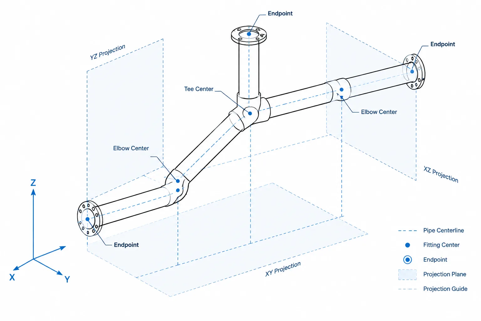
Skewed pipe runs on isometric drawings require a different review approach from piping aligned with the principal project axes. The apparent direction and length of the plotted line cannot establish the actual centerline geometry.
This guide explains how coordinates, endpoint definitions, fitting references, and CAD model checks work together. It also clarifies the important distinction between coordinate movement, true centerline distance, and the cut length of an individual pipe piece.
A piping isometric is not a perspective view and should not be treated as a scale drawing. Its purpose is to communicate connectivity, orientation, dimensions, components, welds, and fabrication information in a compact format. This becomes especially important when a pipe run does not follow the drawing’s principal isometric axes.
These non-orthogonal or skewed pipe runs can represent horizontal diagonal routing, sloped piping, or movement in all three coordinate directions. The line on the sheet may look deceptively simple, but its true geometry depends on coordinates and dimensions rather than its graphic length or angle.
Understanding how to read and check skewed pipe runs helps drafters avoid incorrect cut lengths, misplaced endpoints, and isometrics that cannot be reconciled with the CAD model.
What Is a Skewed Pipe Run?
In plant layout, most pipe segments are routed parallel to one of the project coordinate axes. On an isometric drawing, these segments follow the corresponding isometric directions. A skewed run is different: its centerline is not parallel to a principal axis.
A skew may involve:
- Movement in two horizontal coordinate directions while remaining at one elevation.
- Horizontal movement combined with a change in elevation.
- Movement in all three coordinate directions.
- A deliberately sloped line whose plan direction is also diagonal.
The term describes centerline geometry, not a special pipe product. A skewed run may contain ordinary pipe, elbows, bends, flanges, or other components arranged to achieve the required endpoint and direction.
Why the Drawn Line Is Not the Pipe Length
Isometric drawings compress three-dimensional geometry onto a two-dimensional sheet. Principal directions are drawn using a drafting convention, while skewed segments may be adjusted graphically for clarity. Symbol sizes, fitting representations, and spacing between annotations may also be exaggerated.
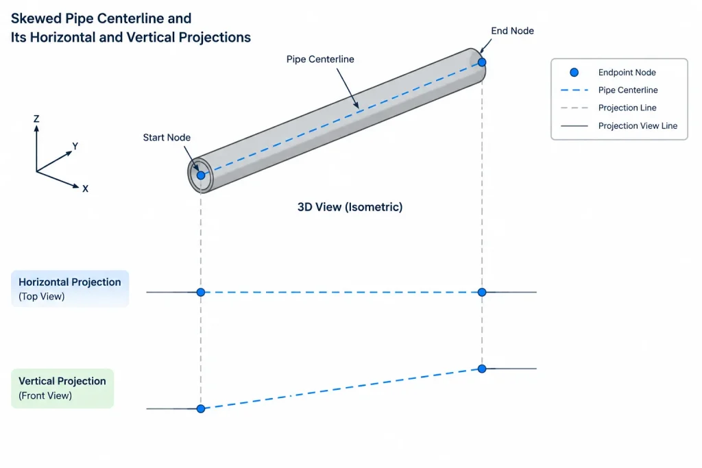
For that reason, measuring the displayed line with a ruler or CAD distance command does not reliably provide the pipe’s true centerline length. Even when an isometric is produced from an accurate model, the plotted graphic may be rescaled or rearranged during drawing generation.
The controlling information should instead come from explicit dimensions, endpoint coordinates, component data, and the verified model. A note stating that a drawing is not to scale reinforces this principle, but the drawing should remain unambiguous even without graphic measurement.
True Length and Coordinate Components
A skewed centerline can be described by its changes in the three project coordinate directions. These coordinate differences are often called component distances, projections, or deltas. They describe how far the endpoint moves along each axis; they are not automatically the pipe’s true length.
For a straight segment, the true centerline length is obtained from the coordinate changes using three-dimensional geometry:
True length = square root of the sum of the squared coordinate changes.
If there is no elevation change, the same principle reduces to a two-direction plan calculation. When fittings are present, however, the result is generally a centerline relationship between defined points—not necessarily the straight pipe cut length. Fitting takeouts, end preparations, engagement, and fabrication allowances must still be applied according to the actual connection arrangement.
| Information | What it describes | Common misuse |
|---|---|---|
| Coordinate change | Movement along one project axis | Treating one projection as the full pipe length |
| True centerline length | Straight-line distance between defined endpoints | Using it directly as cut length through fittings |
| Drawing line length | Graphic representation on the sheet | Scaling it to obtain a fabrication dimension |
| Cut length | Required length of a specific straight pipe piece | Ignoring fitting takeout or connection geometry |
Identify the Points Being Dimensioned
A dimension is useful only when its endpoints are clear. A skewed run may be located using coordinates at welds, fitting centers, tangent points, flange faces, equipment nozzles, or designated tie-in points. These references are not interchangeable.
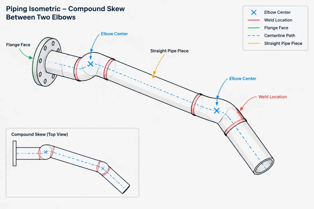
Before checking the geometry, determine whether each callout refers to:
- A pipe centerline intersection.
- The center of an elbow or bend.
- A tangent point on a bend.
- A weld location.
- A flange face or component end.
- An equipment or structural interface.
For example, coordinates at two elbow centers define the center-to-center path between those fittings. They do not directly state the cut length of the pipe between prepared fitting ends. Similarly, a coordinate at a flange face should not be compared with a model point placed at the flange center or mating joint plane without confirming the component origin convention.
Horizontal Skews Versus Sloped Skews
Horizontal diagonal routing
A horizontal skew changes two plan coordinates but remains at a constant centerline elevation. The isometric should make that constant elevation understandable and provide enough plan-direction information to reconstruct the route. Endpoint coordinates are often clearer than an unlabeled diagonal angle.
Sloped routing in one plan direction
A sloped segment changes elevation while advancing along a horizontal axis. The drawing may identify the endpoint elevations, a slope requirement, or both. The designer should verify that the shown dimensions and elevations describe a consistent centerline.
Compound skewed routing
A compound skew changes both plan coordinates and elevation. It needs the most careful documentation because a single displayed diagonal cannot communicate three independent coordinate changes. Clearly defined endpoints or complete coordinate deltas are essential.
Angles, Bearings, and Coordinates
Skewed routing can be defined using angles, coordinate differences, or a combination of both. Coordinates are particularly effective at interfaces because they identify where the run begins and ends in the plant coordinate system. Angles can help fabrication and layout teams understand direction, but an angle alone may not fully locate the endpoint.
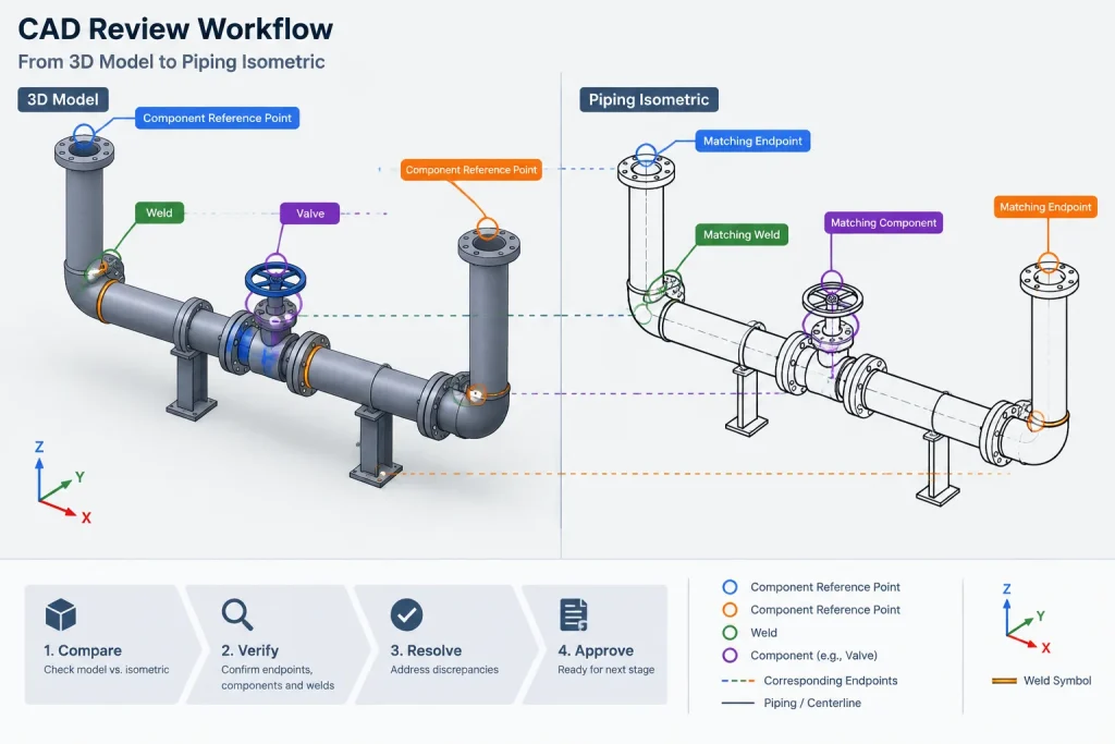
When an angle is shown, its reference must be clear. The reader should not have to guess whether it is measured in plan, from a project axis, from a local equipment axis, or as a three-dimensional included angle. Ambiguous angle callouts are especially risky on compound skews.
A practical drawing hierarchy is:
- Use coordinates or established datum dimensions to locate critical endpoints.
- Use component dimensions to define the intervening assembly.
- Use angle or slope callouts where they improve fabrication understanding.
- Avoid relying on the visual inclination of the drawn line.
CAD Workflow for Checking a Skewed Run
A reliable review starts with model geometry and ends with drawing reconciliation.
- Confirm the coordinate system. Verify project axes, elevation datum, units, and any local coordinate system used around equipment or packaged units.
- Identify the controlling endpoints. Select the same physical references used by the drawing, such as fitting centers, welds, flange faces, or nozzle points.
- Read the coordinate changes. Compare the model’s movement in each axis with the dimensions or coordinates shown on the isometric.
- Check the true centerline distance. Use the modeled centerline or geometric calculation rather than measuring the plotted isometric line.
- Separate centerline geometry from cut length. Account for fittings and connection definitions before assigning a pipe piece length.
- Verify connected-component orientation. Check elbow planes, flange rotation, valve orientation, and branch clocking. Correct endpoints do not guarantee correct intermediate orientation.
- Reconcile the bill of material. Confirm that the fittings needed to create the skew are represented and that no modeling aid has been mistaken for a purchasable component.
- Regenerate and recheck the drawing. Model corrections may alter dimensions, weld positions, spool assignments, or annotation placement.
Common Drafting and Review Errors
- Scaling the isometric: A reviewer measures the diagonal graphic instead of using stated geometry.
- Confusing projections with true length: A coordinate delta is entered as the straight segment length.
- Mixing reference points: A flange face coordinate is compared with a fitting-center coordinate.
- Omitting one axis: A compound skew is dimensioned as if it were a flat plan offset.
- Duplicating dimensions: Coordinates, overall dimensions, and chain dimensions conflict after a revision.
- Ignoring fitting takeout: Center-to-center distance is issued as pipe cut length.
- Showing an undefined angle: The reference axis or plane is not identified.
- Correct endpoint, wrong route: Intermediate elbows or bends are oriented differently from the intended model geometry.
What a Clear Isometric Should Communicate
A skewed run does not need excessive dimensioning, but it does need a complete and consistent geometric definition. A fabricator or checker should be able to determine where the run starts, where it ends, how it changes direction and elevation, and which points control fabrication.
Use the minimum set of non-conflicting dimensions needed to reconstruct the assembly. Critical interface coordinates are usually more valuable than many chained dimensions. If true lengths or cut lengths are listed, label them by purpose so they cannot be confused with coordinate projections.
Most importantly, treat the isometric as a data-rich schematic of the piping assembly—not a picture to be scaled. When coordinate references, component points, and cut-length logic agree, even a complex skewed route can be fabricated and installed with confidence.
Practical Review Strategy
When reviewing a skewed run, begin with the physical references rather than the appearance of the drawing. Confirm what each coordinate or dimension locates, then compare those same points in the model. A valid comparison requires matching references, such as face to face, center to center, weld to weld, or tangent point to tangent point.
Next, separate geometric verification from fabrication-length verification. Endpoint coordinates can confirm the route and true centerline relationship, but they do not automatically provide the cut length between connected fittings. The connection arrangement, fitting geometry, end preparation, and applicable fabrication method remain part of that determination.
Drawing-to-Model Reconciliation
A useful check should answer three questions: Does the run terminate at the intended location? Does it follow the intended direction through each coordinate axis? Are the fittings and connection points represented consistently between the isometric and the model?
If the endpoint is correct but the intermediate routing differs, the assembly may still have incorrect elbow planes, component orientation, branch direction, or spool geometry. For that reason, checking only the overall endpoint distance is not sufficient.
Revision Control for Skewed Geometry
Skewed routing is particularly sensitive to revisions because a change in one coordinate direction can affect the true length, fitting orientation, weld location, and displayed dimensions. After a model change, regenerate the isometric and review the complete dimension set rather than editing an isolated callout.
Conflicting dimensions should be resolved at their source. Avoid leaving redundant coordinate, chain, and overall dimensions that describe different revisions of the same route. The final drawing should provide one consistent geometric definition that can be traced back to the verified model.
Frequently Asked Questions
Can a skewed pipe length be measured directly from an isometric drawing?
No. A piping isometric is a schematic representation and may not preserve graphic scale. Use stated dimensions, coordinates, defined component points, and verified model geometry.
Is true centerline length the same as pipe cut length?
Not necessarily. True centerline length describes the straight-line relationship between defined points. Cut length depends on where the pipe piece begins and ends, including fitting takeout, end preparation, and connection geometry.
Why must coordinate reference points be identified?
A coordinate at a flange face describes a different physical location from a coordinate at a fitting center, weld, tangent point, or joint plane. Comparing unlike references can create an apparent discrepancy even when the model is correct.
How should a compound skew be documented?
The drawing should clearly define movement in every applicable project direction and identify the controlling endpoints. Angle or slope information may support interpretation, but it should not replace the information needed to locate the route.
What should be checked after changing a skewed run in CAD?
Recheck endpoint coordinates, centerline geometry, fitting planes, component orientation, weld locations, spool divisions, dimensions, annotations, and the bill of material. Then regenerate the isometric so the drawing reflects the revised model.
Can correct endpoints still produce an incorrect piping route?
Yes. Different intermediate fitting arrangements can reach the same endpoint. Review elbow planes, bends, branches, valves, flanges, and other components along the complete route.