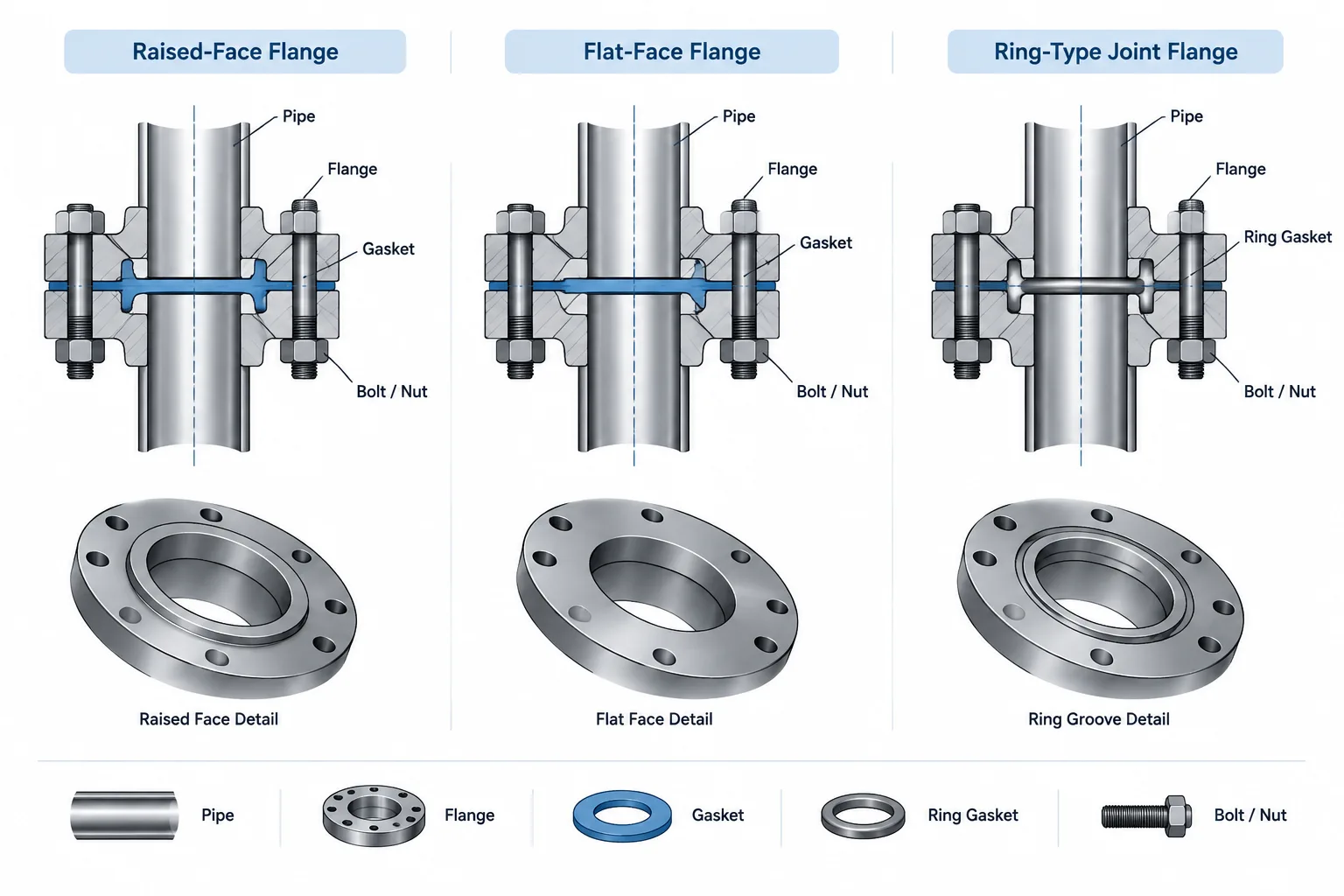
Flange face types in piping CAD must be identified by more than the visible outline of a component. Raised-face, flat-face, and ring-type-joint connections can look similar in a simplified model while requiring different sealing components, mating geometry, and assembly references.
This guide explains how flange facing differs from flange construction, how each sealing arrangement should be represented, and which component properties should remain available when detailed geometry is intentionally omitted.
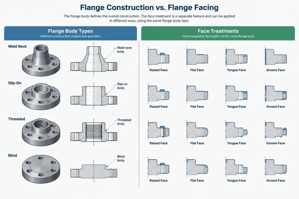
A flange face is the portion of a flange that forms the sealing interface with a gasket and the opposing flange. It is not the same as the flange type. A weld neck, slip-on, threaded, or blind flange describes the flange construction or pipe connection, while terms such as raised face, flat face, and ring-type joint describe the sealing surface.
This distinction matters in piping CAD because two components can share the same nominal size, flange construction, and pressure designation while requiring different face geometry and gasket arrangements. A simplified model may make them look interchangeable even when the actual joint details are not. Designers therefore need to carry flange-facing information as component data, not rely on appearance alone.
Flange type and flange face are separate attributes
A complete flange description usually combines several characteristics. Depending on the project, these can include nominal pipe size, pressure class or other rating designation, material, flange construction, facing, bore, and applicable dimensional standard. A specification may also control the gasket type and facing finish.
For example, identifying a component only as a weld neck flange does not define its sealing surface. Likewise, the abbreviation RF identifies a raised face but does not tell the drafter whether the flange is weld neck, slip-on, blind, or another construction.
In a CAD catalog or component database, these properties should be stored in separate fields whenever possible. Combining everything into an informal description makes filtering, replacement, and material reporting more difficult.
Common flange face arrangements
| Facing | Basic sealing arrangement | Important CAD concern |
|---|---|---|
| Raised face | A defined portion of the face projects beyond the surrounding flange surface, and the gasket is located on that raised area. | Represent the correct face-to-face reference and include the gasket in the joint stack-up. |
| Flat face | The principal contact surface is generally in one plane across the flange face. | Do not substitute raised-face geometry merely because the bolt pattern appears compatible. |
| Ring-type joint | A metallic ring gasket is seated in matching machined grooves. | Model or document the groove-facing designation and use the correct gasket-related joint data. |
| Tongue-and-groove | A projecting tongue mates with a corresponding groove and confines the gasket. | Control which side receives each complementary facing; the two flange faces are not identical. |
| Male-and-female | A raised male face mates with a recessed female face around the gasket. | Track mating-side orientation and avoid pairing two identical faces. |
Raised face
The raised face is widely encountered in industrial piping. Its gasket normally occupies the annular sealing area inside the flange bolting rather than extending across the entire flange diameter. The raised portion affects the axial joint geometry, although the amount and treatment of that projection depend on the governing flange requirements.
A schematic CAD block may omit the small step because it would be difficult to see at the drawing scale. That simplification is acceptable only when the component data still identifies the facing correctly. For fabrication details, section views, joint-stack calculations, or high-detail models, the sealing face should be represented using verified dimensions from the selected component source.
Flat face
A flat-face flange presents a substantially continuous planar contact surface. Full-face gaskets are commonly associated with this arrangement, but gasket selection must come from the piping specification and joint design rather than from a general drafting assumption.
Flat-face and raised-face components should not be mixed casually. Even when bolt holes align, the contact condition and load distribution can differ. Some equipment connections or flange materials may impose specific mating-face requirements. If a nozzle schedule identifies a flat face, the piping model should preserve that requirement through procurement and connection checks.
Ring-type joint
A ring-type-joint facing uses accurately machined grooves in both mating flanges. A shaped metallic ring gasket fits between the grooves and develops the seal as the joint is tightened. The ring is a distinct component and should not be treated as a generic flat gasket in a bill of materials.
RTJ geometry is especially sensitive to component identity. A generic flange outline cannot confirm groove compatibility, gasket selection, or axial dimensions. The model should carry the verified facing and ring information required by the project specification. When detailed groove geometry is unnecessary, metadata and clear callouts remain essential.
Complementary facings
Tongue-and-groove and male-and-female arrangements use unlike but complementary mating faces. This creates an orientation issue that does not exist in a pair of ordinary raised-face flanges. A component substitution or model reversal can place two tongues, two grooves, two male faces, or two female faces together.
Where these facings are used, catalog naming should clearly identify each side. Connection validation should test the facing pair, not simply the nominal size and rating designation.
Facing finish is not the same as facing geometry
The geometric face type describes the overall sealing arrangement. Facing finish describes the machined surface texture or pattern applied to the gasket-contact area. These are related but separate properties.

A CAD model rarely needs to reproduce machining marks as physical geometry. Doing so adds visual complexity without improving most layout work. Instead, record the required finish in the component specification, flange description, fabrication note, or controlled data field. Avoid decorative hatch patterns that could be mistaken for a verified machining requirement.
The selected gasket, service conditions, flange material, assembly method, and governing specification all influence facing requirements. A visually plausible texture in a rendering is not engineering documentation.
How flange facing affects joint length
Flanged-joint length is more than the distance between two basic flange bodies. The assembled stack may include flange faces, a gasket or sealing ring, isolation components, washers, and other specified items. Which dimensions are already included in a manufacturer or standard face-to-face value must be understood before adding anything in CAD.
Common errors include adding a raised-face projection twice, omitting gasket thickness from a custom assembly, or applying a flat-gasket assumption to an RTJ connection. These mistakes can shift equipment, alter spool cut lengths, and create interference with supports or nearby components.
For layout control, establish the connection-plane convention used by the CAD system. A component port might be placed at the gasket contact plane, at the outermost face, or at another catalog reference. All mating components must follow a compatible convention.
Recommended CAD data fields
A practical flange record should keep enough information to distinguish similar-looking components. Useful fields include:
- Nominal size designation
- Flange construction, such as weld neck, slip-on, or blind
- Pressure class or applicable rating designation
- Facing type
- Material specification or project material code
- Bore or schedule-related configuration where relevant
- Gasket category or gasket reference
- Connection-plane or insertion-point convention
- Source and revision status of the verified dimensional record
Do not infer facing from the flange class alone. Do not infer it from line service, material, or the appearance of a simplified block. The piping specification, equipment data, and approved component definition should agree.

Representation at different drawing levels
P&IDs
A P&ID usually communicates process function rather than detailed flange-face geometry. Special joint requirements may be identified by notes, specifications, or project conventions, but the absence of a face symbol does not authorize the 3D designer to choose one.
General arrangements and orthographic drawings
At small scales, flanges are commonly shown schematically. A raised-face step or RTJ groove may be invisible. Use component tags, notes, or extracted data when the facing is important to review.
3D models
The model should contain enough geometry for reliable envelope, connection, and joint-length checks. Detailed grooves and surface finishes are usually unnecessary unless they serve fabrication, visualization, or automated validation. Metadata should remain authoritative even when geometry is simplified.
Fabrication details and isometrics
These deliverables need unambiguous component descriptions and gasket identification. A shop should not have to determine facing from a small line drawing. Special or complementary facings deserve explicit callouts and orientation control.
Flange-face review checklist
- Confirm that flange construction and flange facing are recorded separately.
- Compare piping flange faces with equipment-nozzle and valve-end requirements.
- Verify that mating faces form an intended pair.
- Check that the gasket or sealing ring matches the specified facing arrangement.
- Confirm the CAD connection-plane convention before calculating joint length.
- Ensure the bill of materials does not replace a metallic ring with a generic gasket entry.
- Review transitions between flat-face, raised-face, RTJ, and complementary facings.
- Use verified catalog or project dimensions rather than measuring a schematic block.
- Keep machining-finish requirements in controlled documentation rather than cosmetic model detail.
A flange that fits visually may still be wrong
Flange-facing errors are easy to hide in CAD because bolt circles and outside profiles can appear compatible. The decisive information lies at the sealing interface: face geometry, gasket arrangement, mating-face compatibility, and the dimensional reference used for assembly.
Separating these attributes in the component database gives designers a more dependable workflow. Geometry supports layout, metadata supports specification control, and both should be checked against verified project requirements before a flange joint is released for fabrication or construction.
Use facing data throughout the CAD workflow
Facing information should remain attached to the component as it moves from specification selection through modeling, drawing extraction, material reporting, and fabrication review. If that property exists only in a note or an informal description, it can be lost when a flange is copied, replaced, or exported.
A useful review begins with the piping specification and approved component record, then compares the selected flange with the mating valve, equipment nozzle, or adjoining flange. The gasket or sealing ring should be checked as part of the same connection rather than as an unrelated material item.
Control substitutions by connection compatibility
Replacing a flange based only on nominal size, flange construction, or bolting appearance can preserve the visible layout while changing the sealing interface. Catalog substitution rules should therefore compare facing and mating requirements before accepting a replacement.
Complementary faces require additional orientation control because the two sides perform different roles. Ring-type-joint connections also require the sealing ring to retain its distinct identity in component data and material reports.
Separate model detail from engineering authority
A detailed model can help with section views and joint visualization, but geometry alone should not be treated as the governing specification. Conversely, a schematic flange can remain useful for layout when its metadata clearly records the approved face type, gasket arrangement, and dimensional source.
This separation allows drafting teams to use an appropriate level of detail without losing the information needed for connection validation, procurement, or fabrication review.
Frequently asked questions
Is a raised face a type of flange?
No. Raised face describes the sealing surface. Weld neck, slip-on, threaded, and blind describe flange construction or connection form. A complete component description may need both attributes.
Can a flat-face flange be connected to a raised-face flange?
Do not assume that the connection is acceptable because the bolt holes align. The mating arrangement, gasket, equipment requirements, flange materials, and applicable project specification must be reviewed before the joint is approved.
Does an RTJ flange use a conventional flat gasket?
A ring-type-joint connection uses a shaped metallic sealing ring seated in matching machined grooves. The ring should be identified as its own component rather than represented as a generic flat gasket.
Must CAD models include the RTJ groove?
Not in every model. Detailed groove geometry may be unnecessary for general layout, but the component data and drawing callouts must still identify the facing correctly. Verified geometry should be used when the groove affects the intended deliverable or validation process.
Should machining finish be modeled on the flange face?
Usually, the finish is better controlled through specifications, notes, or component data than through decorative model geometry. Facing finish and facing geometry are separate properties, and a rendered texture is not a substitute for engineering documentation.
Why can flange facing affect piping layout?
The facing and sealing component contribute to the assembled joint reference. An incorrect connection-plane convention or duplicated face allowance can shift adjoining components and affect spool or equipment positioning.