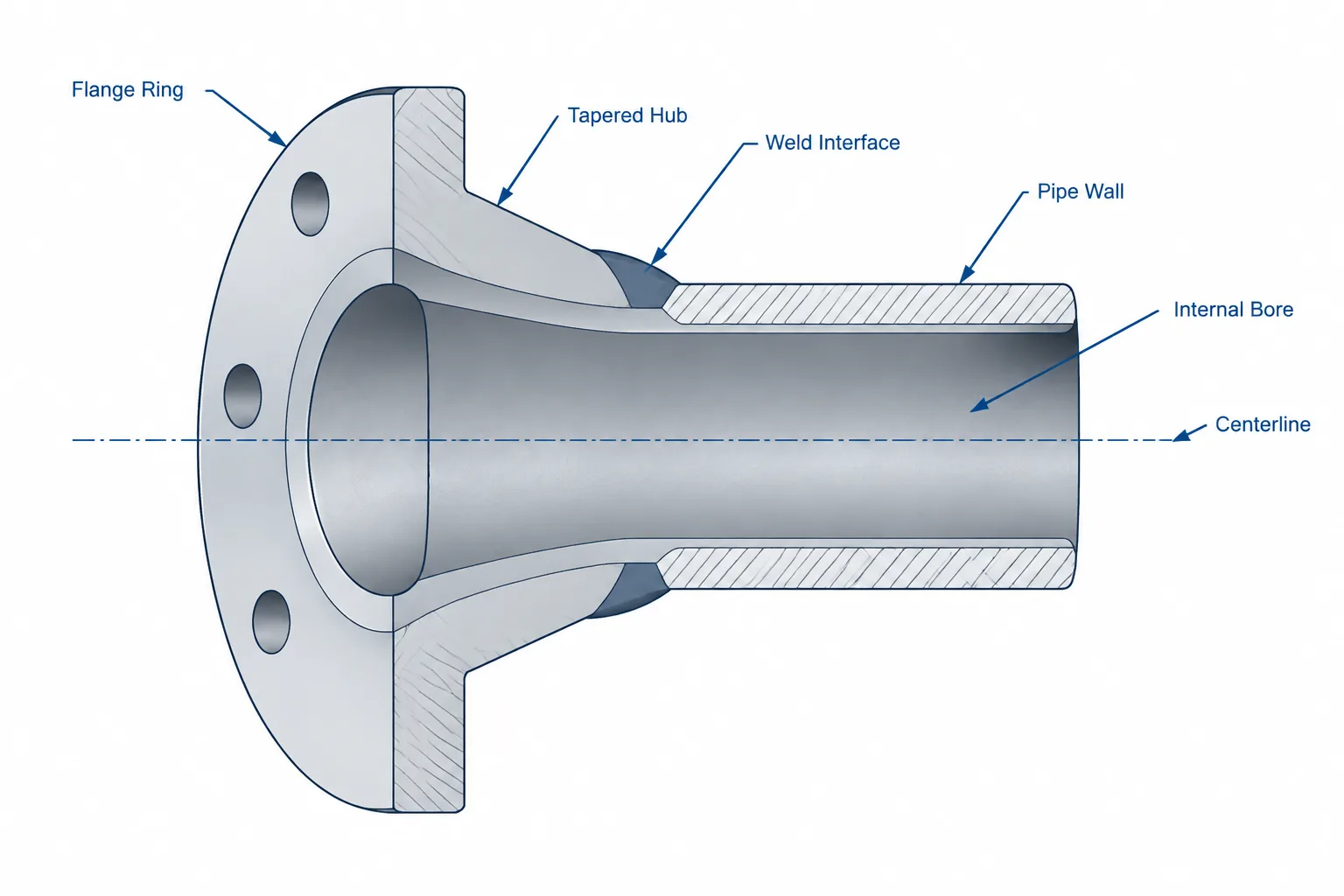
Choosing a weld neck flange in CAD involves more than matching its nominal size, pressure class, and facing. The modeled bore at the pipe end must also correspond to the connected pipe wall and the intended butt-weld interface.
This guide explains how to evaluate that relationship without treating simplified CAD geometry as fabrication approval. It is intended for piping designers, drafters, engineers, and catalog administrators who need component graphics, properties, and material descriptions to remain consistent.
A weld neck flange is often selected in a piping model by nominal pipe size and pressure class. Those properties are important, but they do not fully define the connection. The flange bore must also be compatible with the pipe wall and the intended butt-weld detail.
This issue is easy to overlook because pipes with the same nominal size generally share an outside diameter even when their wall thicknesses differ. A generic flange model may therefore connect cleanly to the pipe exterior while hiding a mismatch inside the bore. The result can be misleading CAD geometry, an incomplete material description, or a fabrication question that appears later than it should.
Designers do not need to model every weld preparation to manage this interface correctly. They do need to understand which dimensions control the connection, where verified data should come from, and when a bore mismatch requires engineering or fabrication review.
What the weld neck flange bore represents
The bore is the internal opening through the flange neck. At the pipe end of a weld neck flange, this opening meets the pipe bore at a circumferential butt weld. Ideally, the selected flange and pipe create an appropriate transition for the applicable design, material, fabrication, and inspection requirements.
The flange bore should not be confused with any of the following:

- Nominal pipe size: a size designation used to coordinate pipe and component connections.
- Pipe outside diameter: the exterior diameter used at the flange-to-pipe alignment interface.
- Pipe inside diameter: a value determined by outside diameter and actual wall thickness.
- Flange face opening: the visible central opening at the gasket face, which is part of the flange geometry but does not by itself describe the pipe-end weld transition.
- Hub outside profile: the tapered exterior shape that transfers load between the flange ring and neck.
A flange can therefore have the correct nominal size, bolt pattern, face geometry, and outside connection diameter while still having a bore that needs closer review.
Why pipe schedule matters
For a given nominal pipe size, changing the pipe schedule changes the nominal wall thickness and resulting inside diameter. It usually does not create a new outside diameter. The flange neck still aligns to the same pipe exterior, but the internal relationship may change.
A thinner-wall pipe has a larger bore than a thicker-wall pipe of the same nominal size. If one generic flange bore is used for both, the internal transition cannot be identical in each case. Depending on the selected component and project requirements, the flange may need a bore associated with the pipe wall, a specified machining condition, or a reviewed weld transition.
This is why a CAD catalog entry labeled only with nominal size and pressure class may be insufficient. The correct flange definition may also depend on schedule, wall designation, specified bore, flange material, and procurement description.
Pressure class does not define the pipe wall
Pressure class and pipe schedule are different classification systems. Pressure class identifies a flange rating category used with the applicable material and temperature basis. Pipe schedule identifies a nominal wall-thickness series. One should not be substituted for the other.
A high-pressure-class flange is not automatically bored for every heavy-wall pipe that might be connected to it. Likewise, selecting a heavy pipe schedule does not automatically determine the required flange pressure class. The piping specification must establish both sides of the selection, and the component description must identify enough information for procurement and fabrication.
| Property | What it primarily controls | Why it matters in CAD |
|---|---|---|
| Nominal pipe size | Basic connection size | Coordinates the pipe, flange, gasket, and mating component size designation |
| Pipe schedule or wall | Nominal pipe wall thickness | Affects the pipe bore and the internal weld transition |
| Flange pressure class | Rating category under the governing specification | Affects the selected flange series and its verified dimensions |
| Flange facing | Gasket seating interface | Controls joint stack-up and mating-face compatibility, not the pipe-end bore by itself |
| Flange bore | Internal opening through the neck | Must be checked against the connected pipe wall and weld detail |
| End preparation | Geometry prepared for welding | Affects fabrication detail and the interpretation of component end points |
What a bore mismatch looks like
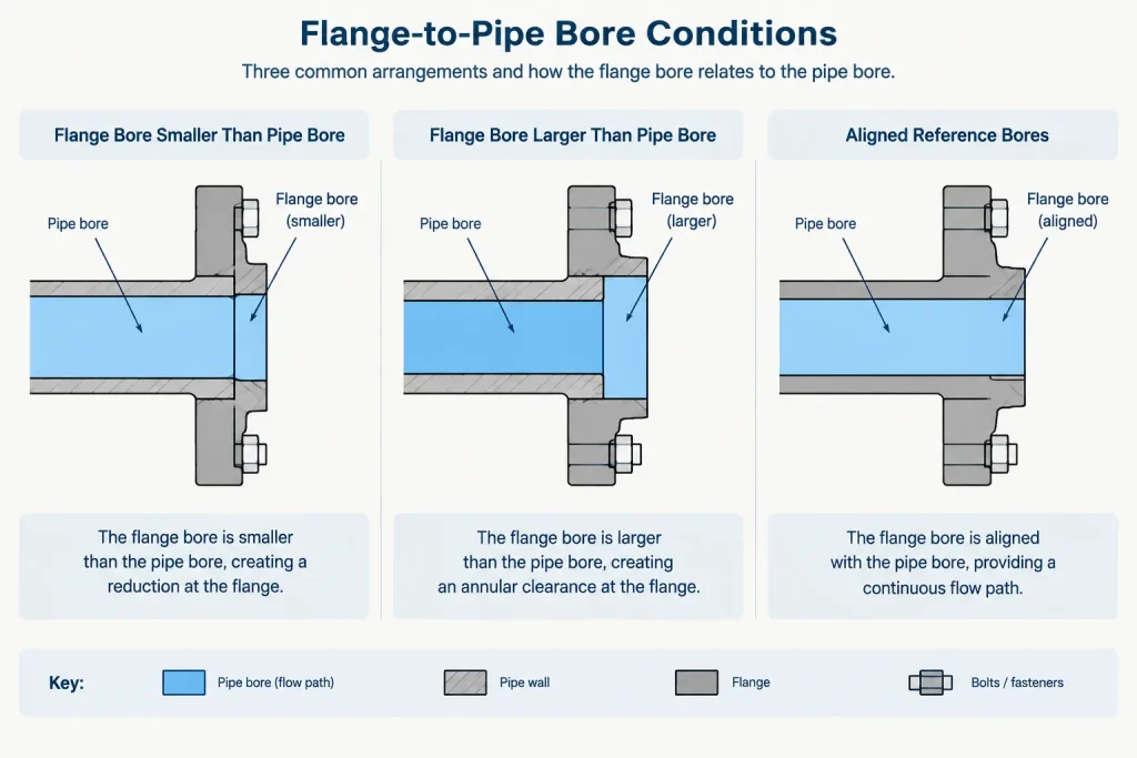
A bore mismatch occurs when the inside surfaces of the pipe and flange neck do not meet at the same radial position. In a section view, the mismatch appears as an internal step at the weld joint.
Not every visible step has the same significance. The direction and magnitude of the mismatch, the component wall, the weld preparation, the service, and the governing project requirements all matter. A simplified CAD section cannot determine acceptability by itself.
Common conditions include:
- Flange bore smaller than pipe bore: the neck projects inward relative to the pipe inside surface.
- Flange bore larger than pipe bore: the pipe wall projects inward relative to the flange neck.
- Nominally matched geometry: the reference bores align in the model, although manufacturing tolerances and actual wall thickness may still produce a physical offset.
- Machined or transitioned bore: the flange or adjoining detail is intentionally prepared to create the specified transition.
Designers should avoid solving the issue by arbitrarily stretching the flange neck or scaling the component. Such edits can corrupt the hub profile, face-to-end dimension, mass properties, connection data, and bill-of-material identity.
How much geometry should the CAD model show?
The required level of detail depends on the model purpose. A layout model may use a simplified solid with a nominal bore because its main tasks are routing, envelope control, and interference checking. A fabrication model or sectional detail may need a more accurate representation of the pipe wall, flange neck, bevel, and internal transition.
For general arrangement and routing models
- Use verified overall and connection dimensions.
- Keep ports and centerlines correctly aligned.
- Store schedule or wall information as component data even if the bore is simplified.
- Do not imply that schematic internal geometry is a fabrication detail.
For spool and fabrication deliverables
- Confirm the ordered flange bore or wall designation.
- Represent the correct pipe wall where section geometry affects the detail.
- Distinguish finished component dimensions from weld gaps and preparation geometry.
- Show machining, tapering, or transition requirements only when they are supported by approved project information.
A practical library can contain a lightweight flange representation for layout and a controlled detailed representation for fabrication views. Both should reference the same component identity so that graphics and material data do not drift apart.
A reliable CAD selection workflow
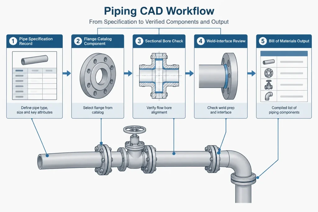
- Read the piping specification. Identify the required flange type, nominal size, class, facing, material, end preparation, and any schedule or bore qualifier.
- Confirm the connected pipe definition. Check nominal size, material specification, schedule, wall designation, and whether corrosion or mechanical allowances are handled as design data rather than modeled geometry.
- Select verified flange dimensions. Use the governing dimensional source, approved catalog data, or project-controlled component library. Do not infer a bore from the outside profile.
- Compare the pipe and flange bores. A section view or automated property check can reveal whether the modeled internal surfaces align.
- Review the weld transition. If the bores differ, determine whether the piping specification or fabrication detail already addresses the condition. Escalate unresolved cases rather than inventing a transition.
- Keep the component description complete. The model property set and material output should carry any bore, schedule, wall, or machining designation needed to distinguish the flange.
- Check mating-joint data separately. Gasket, facing, bolting, and flange alignment remain necessary checks even when the pipe-end bore is correct.
Common modeling and documentation errors
- Selecting a flange by nominal size and class while ignoring a schedule-dependent bore description.
- Assuming that matching outside diameters guarantee matching bores.
- Using one detailed flange solid for every pipe wall without identifying its internal geometry as simplified.
- Confusing flange facing geometry with the neck bore at the welded end.
- Changing a solid manually without updating the catalog record or bill-of-material description.
- Showing a smooth internal transition in a fabrication detail when no verified machining or weld instruction supports it.
- Treating nominal CAD surfaces as proof that actual manufactured components will be flush after fit-up.
What to verify before issuing the drawing
Before issue, confirm that the flange tag or material description resolves to the intended component, the connected pipe wall matches the line class, and the flange bore information comes from a controlled source. Check that the flange end point is located correctly and that weld preparation has not accidentally changed the pipe cut length.
Where internal alignment is important, include a section or detail that communicates the verified condition without over-specifying the fabricator’s method. Any special boring, tapering, or transition requirement should be traceable to project engineering information rather than an assumption made during modeling.
The central lesson is simple: a weld neck flange is not fully defined by its visible ring, bolt holes, and nominal connection size. The bore and neck form the transition into the pipe. Managing that interface as both geometry and component data helps prevent catalog errors, procurement ambiguity, and late fabrication questions.
Managing bore data in a CAD library
A dependable component library should separate verified flange attributes from graphical simplifications. If a flange model uses a representative internal opening, its metadata should make that limitation clear. A detailed bore should not be presented as exact unless it is tied to controlled component information.
Catalog governance is especially important when several flange records share a similar exterior shape. Distinct records may be required when the procurement description, pipe-wall compatibility, end preparation, or machining requirement changes. Reusing one solid under several descriptions can hide meaningful differences unless the library has controlled parameters and validation rules.
Useful quality-control checks
- Property consistency: Confirm that the graphical component and its catalog record identify the same flange type, size designation, class, facing, material, and applicable bore qualifier.
- Connection logic: Check that the flange port aligns with the pipe axis and that its connection definition does not incorrectly imply bore compatibility.
- Section review: Inspect the pipe-to-neck interface when internal geometry is relevant to the deliverable.
- Material output: Verify that the bill of materials retains the information needed to procure the intended flange rather than a visually similar alternative.
- Revision control: Treat a change to bore geometry or component identity as a controlled library update, not an isolated model edit.
Geometry is not acceptance criteria
A CAD model can expose a possible internal offset, but it cannot establish whether that offset is acceptable. That decision depends on the approved piping specification, component data, weld requirements, fabrication procedures, inspection basis, and engineering review.
Designers should document the selected condition and flag unresolved discrepancies. They should not create an unsupported taper, machining instruction, or weld profile merely to make a section view look smooth. The most useful model is not always the most visually detailed one; it is the model whose geometry and properties accurately communicate what is known, what is simplified, and what still requires resolution.
Frequently Asked Questions
Does nominal pipe size determine a weld neck flange bore?
No. Nominal pipe size coordinates the basic connection size, but it does not by itself define the connected pipe wall or the required flange bore. The complete component description and controlled dimensional information must be reviewed.
Can pressure class be used to infer pipe schedule?
No. Pressure class and pipe schedule describe different aspects of the piping system. The piping specification must establish the required flange rating category and the connected pipe-wall designation independently.
Does a clean exterior fit prove that the bores match?
No. Pipes of the same nominal size can share an outside diameter while having different wall thicknesses and inside diameters. The exterior can align even when a section view reveals an internal step.
Should every layout model include a detailed weld preparation?
Not necessarily. Layout and routing models may use simplified internal geometry when that limitation is understood and the required component properties are retained. Fabrication-oriented deliverables may require more detail based on approved project information.
Can a designer machine or taper the bore in the CAD model to remove a mismatch?
Only when the modification is supported by approved engineering, procurement, or fabrication information. An arbitrary graphical transition can misrepresent the ordered component and create an unsupported fabrication requirement.
What should happen when the catalog bore and pipe bore do not agree?
Verify both records against controlled sources, review the piping specification and weld detail, and escalate the unresolved condition. Do not scale the flange or alter its neck solely to force visual alignment.